
Method, system and article of manufacture for identifying the source type and quality level of a video sequence

a video sequence and source type technology, applied in the field of video image processing, can solve the problems of no longer yielding such a low value, the method described above suffers from a number of problems when used with imperfect real-world sources, and the number of objectionable artifacts, etc., to achieve the effect of reducing the number of motion artifacts in video images

Inactive Publication Date: 2005-03-15
LATTICE SEMICON CORP
View PDF78 Cites 79 Cited by
  • Summary
  • Abstract
  • Description
  • Claims
  • Application Information

AI Technical Summary

Benefits of technology

[0025]The present invention advantageously allows for the reduction of motion artifacts in video images. By correctly determining the source type and quality level of a video sequence, a video deinterlacer uses the information to combine fields which are time correlated and to process the image for motion artifacts in the case when fields are not time correlated. The result is a progressive video image which is free of defects and motion artifacts.

Problems solved by technology

Unfortunately, many techniques for deinterlacing the video signal add a number of objectionable artifacts to the resultant progressive image.
The methods described above suffer from a number of problems when used with imperfect real-world sources.
However, and with reference to FIG. 6, for noisy sources a comparison of ‘identical’ fields no longer yields such a low value since noise causes the computation to return a ‘low’ value 60 that exceeds the threshold 62.
A number of other problems are present in real-world video sources.
There are many possibilities for injection of noise into a signal, including poor Y / C separation, imperfect storage media, transmission noise, and digital compression artifacts.
Other factors which can make identification of the source type difficult include video edits made without regard to a progressive source sequence, transitions between different source types, frame rate conversion of a video sequence, and mixing of multiple or unsynchronized source types within a single video frame.

Method used


Image

  • Method, system and article of manufacture for identifying the source type and quality level of a video sequence
  • Method, system and article of manufacture for identifying the source type and quality level of a video sequence
  • Method, system and article of manufacture for identifying the source type and quality level of a video sequence

Examples


Embodiment Construction

f a 2:2 pulldown video source by a vertical high-frequency detection technique;

[0032]FIG. 5 illustrates the prior art behavior of a fixed threshold detection scheme for a well-behaved 3:2 pulldown video source;

[0033]FIG. 6 illustrates the prior art behavior of a fixed threshold detection scheme for a poorly-behaved 3:2 pulldown video source;

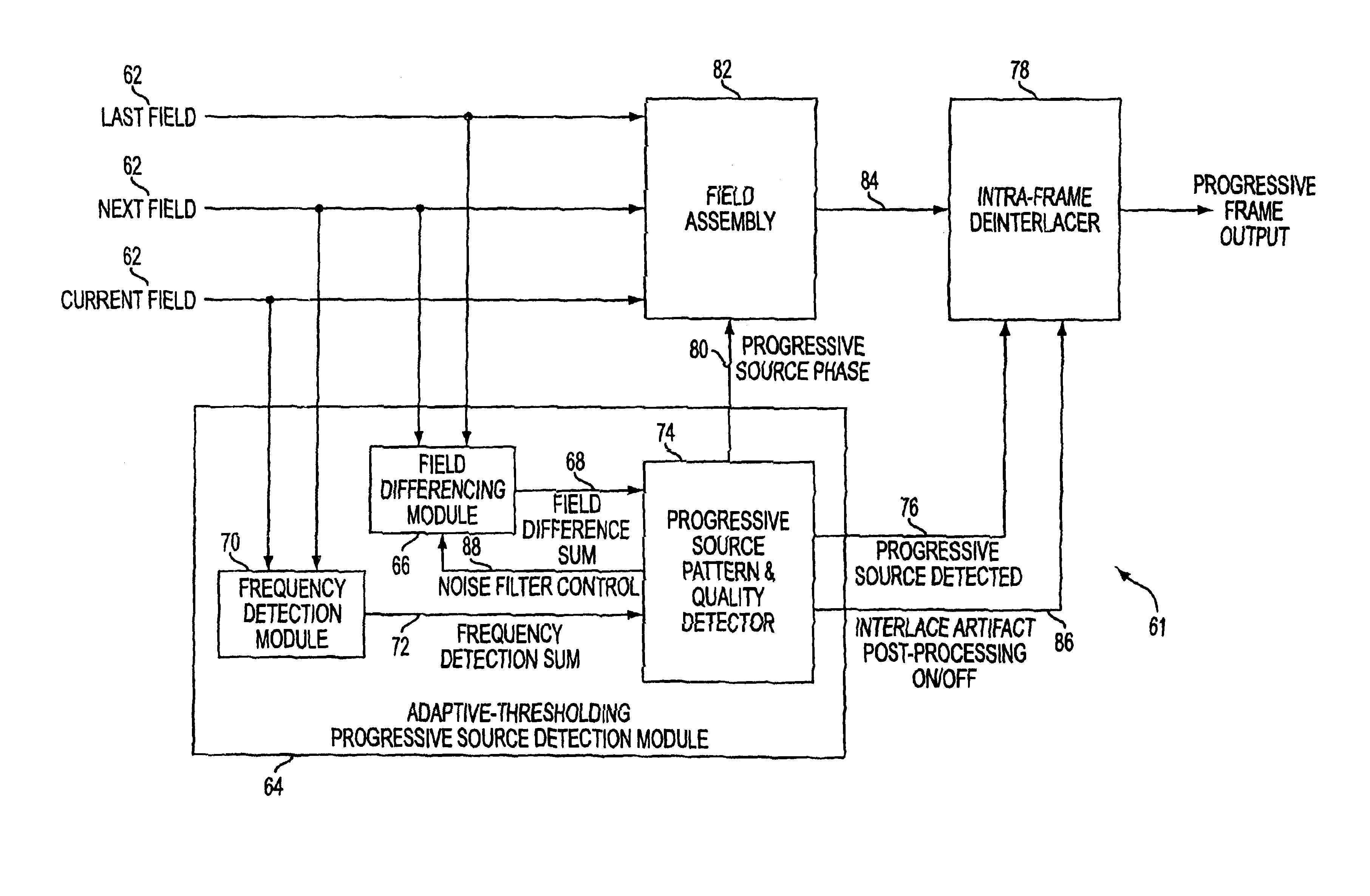
[0034]FIG. 7 is a block diagram of the source detector of the present invention;

[0035]FIG. 8 illustrates the analysis of a 3:2 pulldown video source by a vertical high-frequency detection technique of the present invention;

[0036]FIG. 9 illustrates the behavior of the adaptive threshold detection scheme of the present invention for a poorly-behaved 3:2 detection video source;

[0037]FIG. 10 illustrates the analysis of a 3:2 pulldown video source by a field differencing technique of the present invention which also includes analysis of field difference pair values; and

[0038]FIG. 11 illustrates the analysis of a transition between a 3:2 pulldown video...


PUM


Abstract

A deinterlacing system which converts an interlaced video stream into a progressive video stream is disclosed. The deinterlacing system includes a field assembly responsive to a last field, a next field, a current field and progressive source phase and operative to develop a progressive output frame, a source detection module responsive to last, next and current fields and operative to develop a progressive source phase and a progressive source detected and an intra-frame deinterlacer responsive to the progressive output frame and the progressive source detected and operative to develop a progressive frame output.

Description

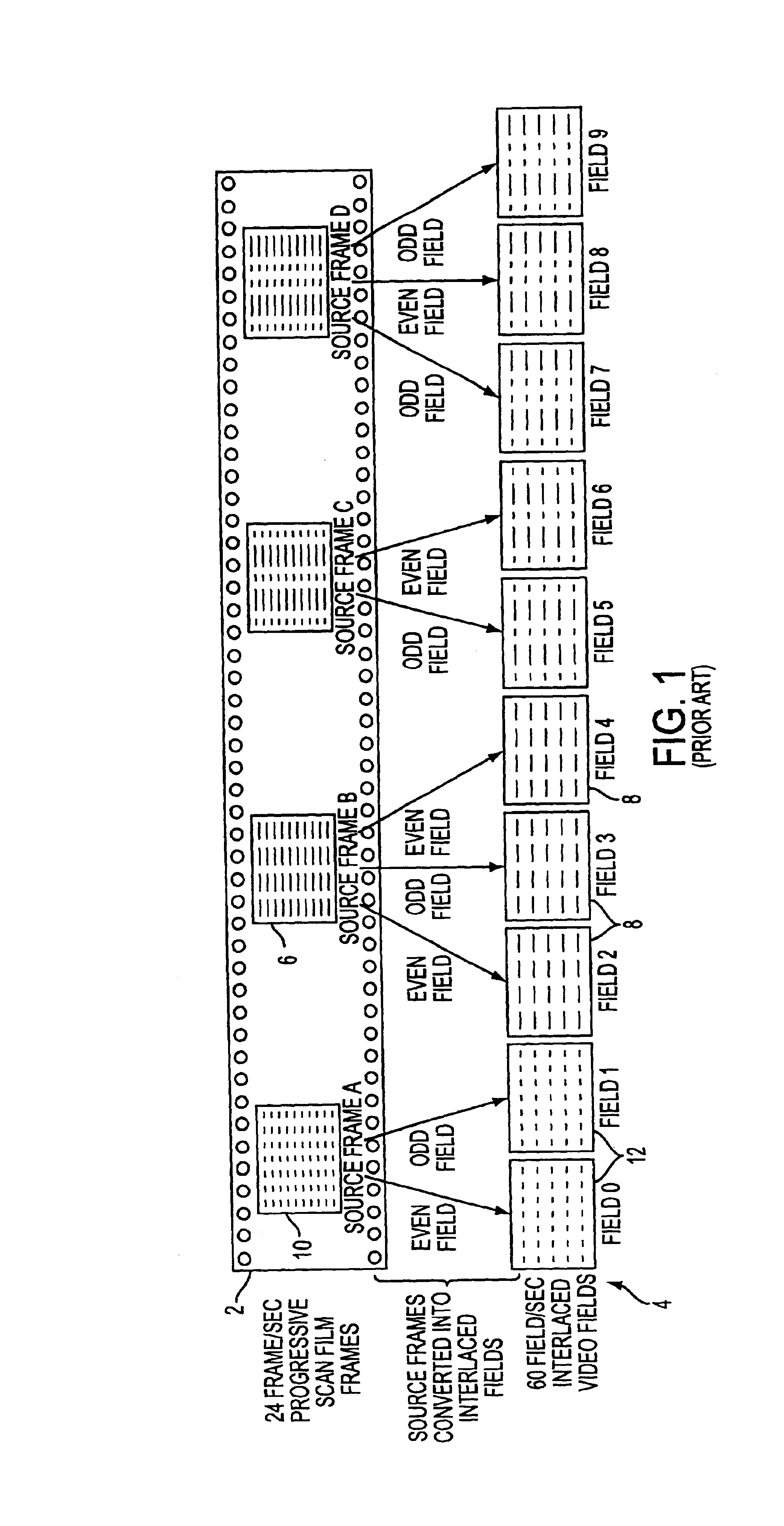
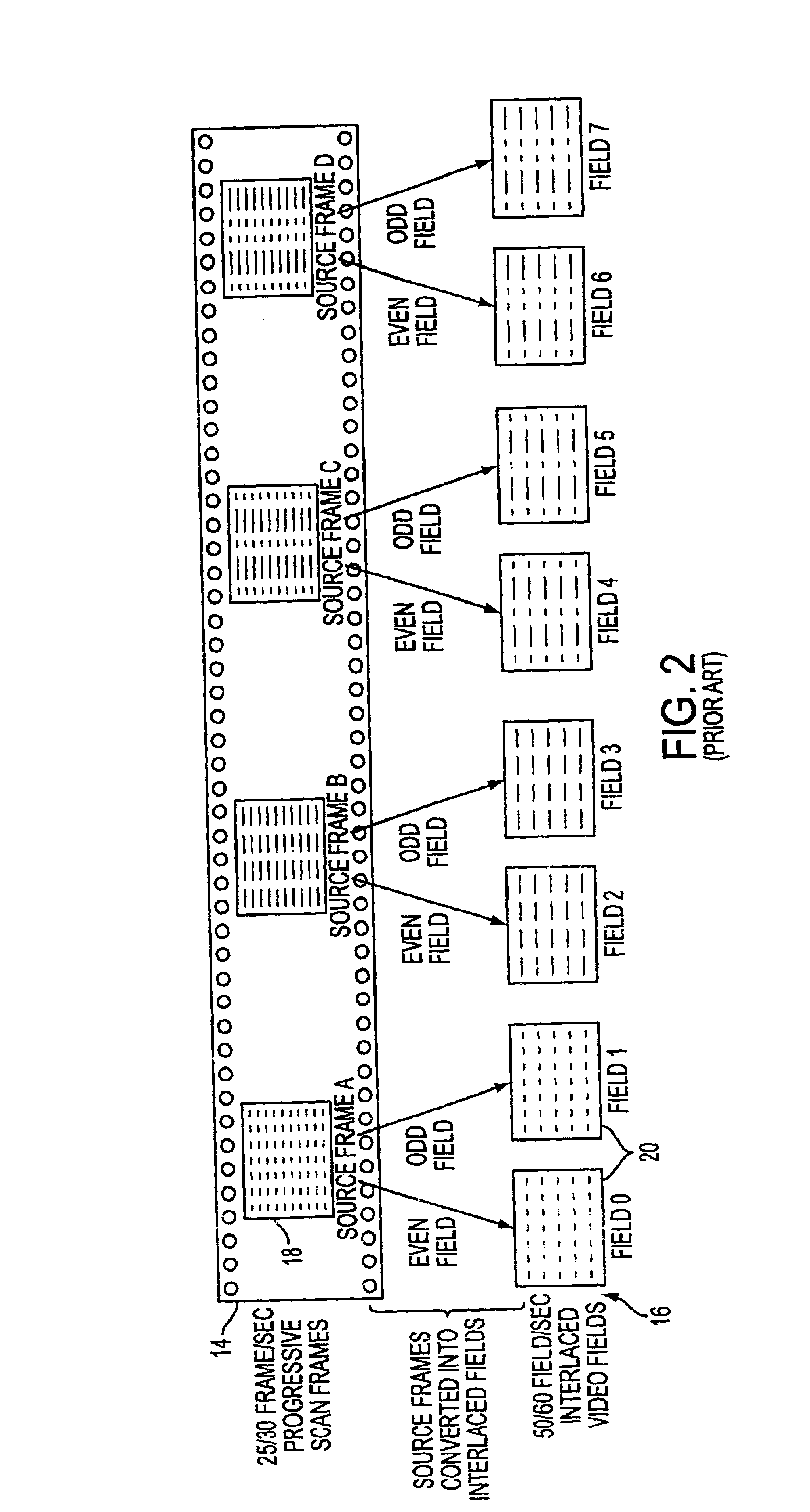
CROSS REFERENCE TO RELATED APPLICATIONS[0002]This application claims the benefit of U.S. Patent Provisional Application No. 60 / 198,044 filed on Apr. 18, 2000, now abandoned, and is related to U.S. patent application Ser. No. 09 / 372,713 filed on Aug. 11, 1999 and U.S. patent application Ser. No. 09 / 410,543 filed on Oct. 10, 1999, assigned to the assignee of the present invention, all of which are incorporated herein by reference.BACKGROUND OF THE INVENTION[0003]1. Field of the Invention[0004]The present invention relates generally to the processing of video images, and more particularly to an adaptive and accurate method and apparatus for identifying the source type and quality level of a video sequence[0005]2. Description of the Related Art[0006]The world's major television standards use a raster scanning technique known as “interlacing.” Interlaced scanning draws horizontal scan lines from the top of the screen to the bottom of the screen in two separate passes, one for even number...

Claims


Application Information

Patent Timeline
IPC IPC(8): H04N7/01H04N5/44H04N5/46
CPCH04N7/012H04N7/0112H04N5/46H04N21/440218
Inventor ADAMS, DALE R.SHEET, WILLIAM
Owner LATTICE SEMICON CORP
Learn More