
Phototherapeutic treatment methods and apparatus

a technology of phototherapy and treatment methods, applied in the field of phototherapy, can solve the problems of inability to fully understand the mechanism that produces the beneficial effect, the liver of a child may be too young to conjugate bilirubin, and the potential to damage biomolecules, etc., and achieve the effect of detailed understanding the mechanism and achieving the beneficial effect of treatmen

Inactive Publication Date: 2005-03-15
INT TECH CENT
View PDF45 Cites 209 Cited by
  • Summary
  • Abstract
  • Description
  • Claims
  • Application Information

AI Technical Summary

Problems solved by technology

However, during the initial neonatal period the infant's liver may be too immature to conjugate bilirubin.
However, UV radiation produces ionization and therefore has the potential to damage biomolecules.
Yet, a detailed understanding of the mechanism that produces the beneficial effect has not been achieved in many treatments.
But, laser beams quickly lose coherence and polarization due to scattering upon entering tissue.
So, many of the reputed advantages due to these properties of laser beams may be lost.
Since LDs and LED sources of radiation are small three-dimensional semiconductor devices that act as point sources of light, they cannot provide uniform doses of radiation over the treated surface of the body.
When several specific wavelengths are required, several types of laser diodes or LEDs with different emission wavelengths are used within an array, making it yet more difficult to achieve uniform irradiation of a particular wave length.

Method used


Image

  • Phototherapeutic treatment methods and apparatus
  • Phototherapeutic treatment methods and apparatus
  • Phototherapeutic treatment methods and apparatus

Examples


example

Treatment Protocol for Treatment of Chronic Wounds

In accordance with one exemplary treatment protocol, an EL light source is believed suitable for phototherapy treatment when the patient has been diagnosed with a chronic wound. A treatment protocol has been established by Salansky et al. and others that specifies that chronic ulcers or wounds can be treated by exposure to light in the range of 600-700 nm at a dosage of 0. 05 to 0.2 J / cm2 and power densities from 0.2 to 10 mW / cm2. This can be accomplished with a treatment period of approximately 0.33 minutes using a 10 mW / cm2 source for 0.2 J / cm2 dose. Since an organic TFEL light source using, for example, Erbium or Europium as a dopant can produce a light spectrum in this range, with an intensity of approximately 0.5-1 mW / cm2 exposure of the affected tissue to light from a TFEL light source of this type is believed appropriate to provide a similarly effective phototherapy by adjusting the exposure time to approximately between 3.3 a...


PUM


Abstract

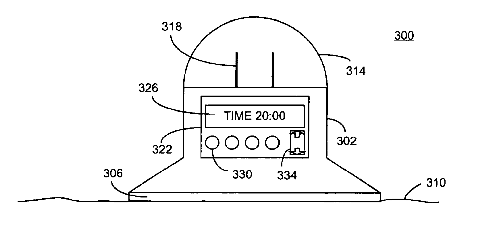
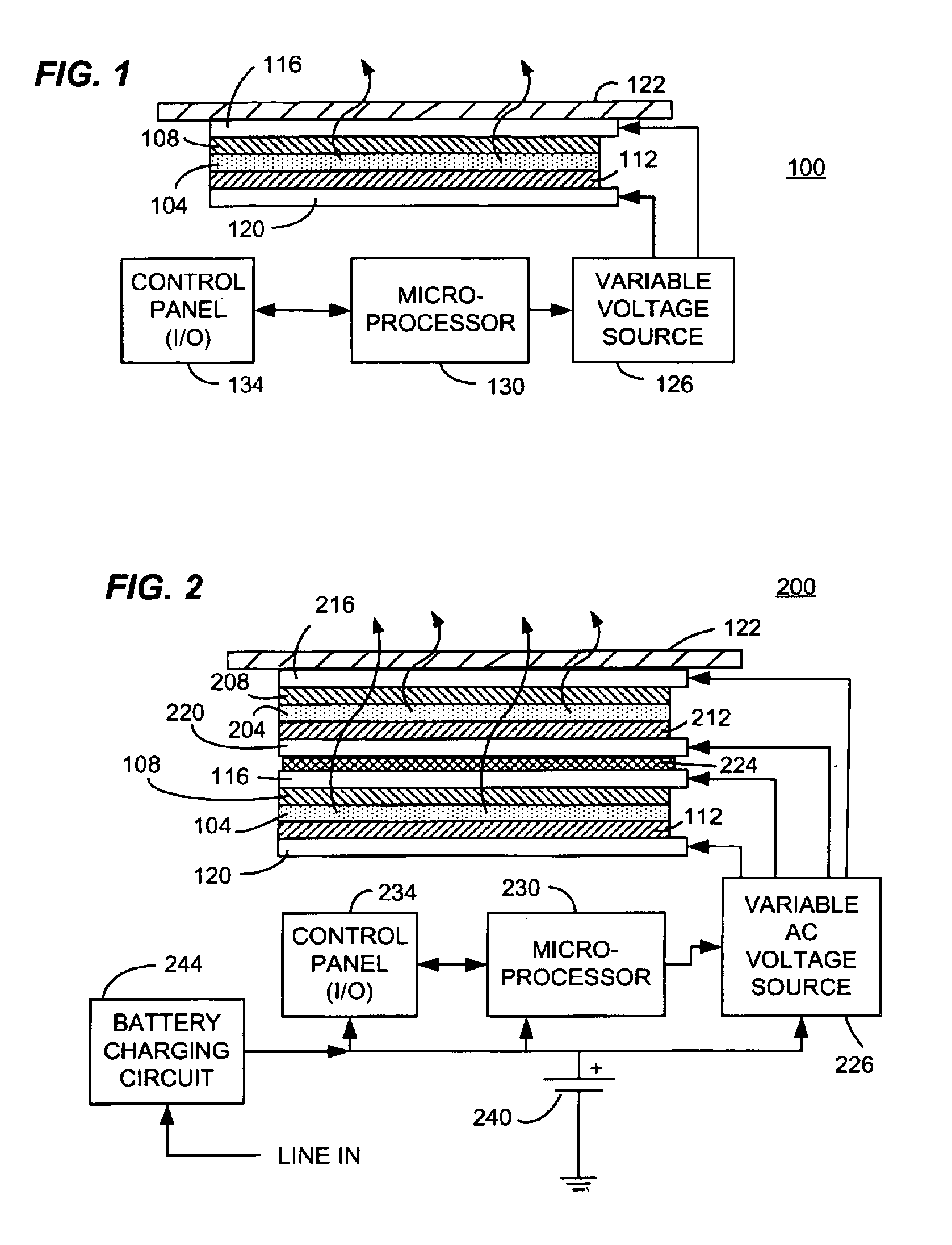
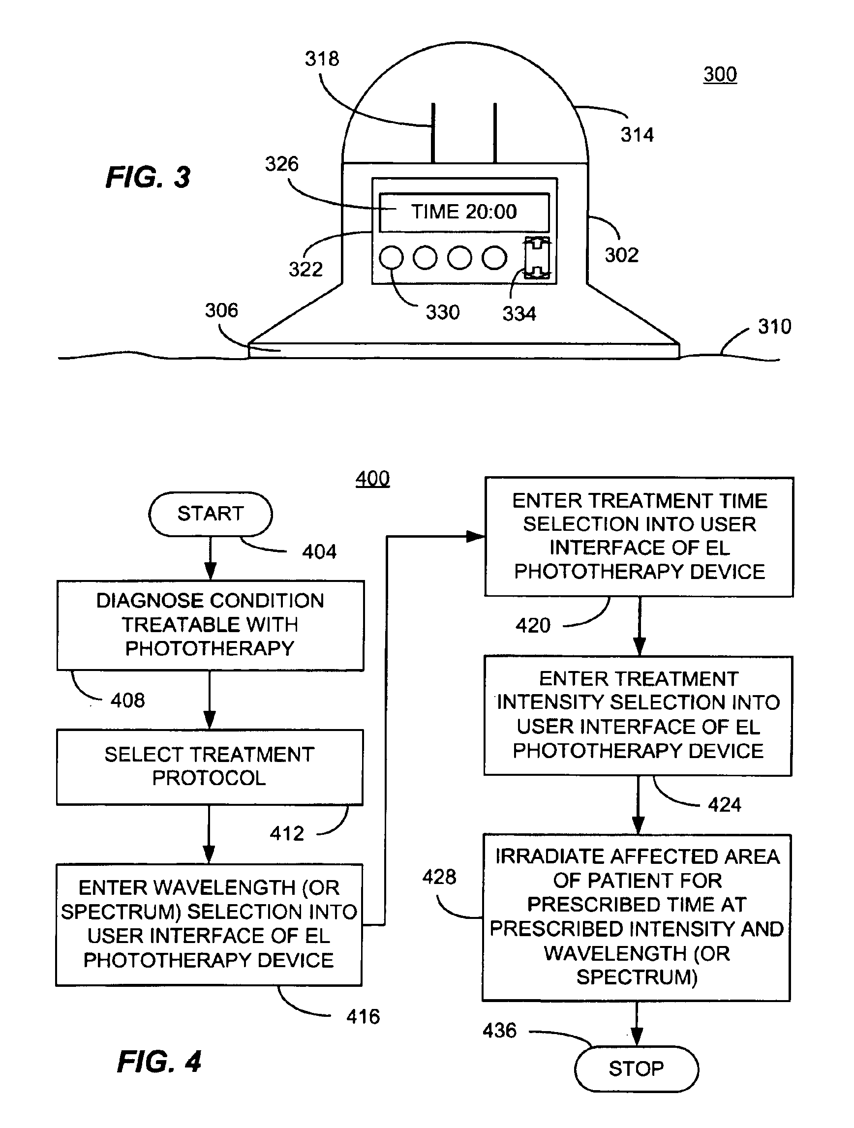
A thin film electroluminescent (TFEL) phototherapy device based on high field electroluminescence (HFEL) or from organic light emitting devices (OLED), consistent with certain embodiments of the present invention has a battery and a charging circuit coupled to the battery, so that when connected to a source of current acts to charge the battery. A TFEL panel produces light when voltage from the power source (battery or AC source) is applied. A processor such as a microprocessor is used to control the application of voltage from the power source to the TFEL panel under control of a control program. A housing is used to contain the battery, the charging circuit and the processor and carry the TFEL panel on an outer surface thereof. In one embodiment, the housing incorporates a removable cover that uncovers a household electrical plug useful for supplying charging current to the charger. In use, a method of carrying out phototherapy, consistent with certain embodiments of the invention involves diagnosing a condition of an affected area of tissue that can be treated with phototherapy. A treatment protocol is determined including, for example, a treatment light intensity, a treatment time, a light modulation characteristic and a treatment light wavelength suitable for treating the condition. The affected area is then irradiated with light from the TFEL panel in accord with the treatment protocol.

Description

FIELD OF THE INVENTIONThis invention relates generally to the field of phototherapy. More particularly, this invention in certain embodiments relates to methods and apparatus for phototherapy using a thin film electroluminescent (TFEL) light source.TABLE OF AUTHORITIESThe following authorities are cited by number in the text follow:1. Whelan, H. T. et al., Effect of NASA light-emitting diode irradiation on wound healing, J.Clin.Laser Med.Surg. 19:305-314, 20012. Karu, T., Primary and secondary mechanisms of action of visible to near-IR radiation on cells, 49:1-17, 19993. Karu, T., The Science of Low-Power Laser Therapy, Gordon and Breach Sci. Publ., 19984. Gupta, A. K. et al., The use of low energy photon therapy (LEPT) in venous leg ulcers: a double-blind, placebo-controlled study, Dermatol.Surg. 24:1383-1386, 1998;5. Cowen, D., et al., Low energy Helium-Neon laser in the prevention of oral mucositis in patients undergoing bone marrow transplant: results of a double blind randomize...

Claims


Application Information

Patent Timeline
IPC IPC(8): A61N5/06
CPCA61N5/0616A61N5/062A61N2005/0653A61N2005/0652A61N5/0621
Inventor SHENDEROVA, OLGAMCGUIRE, GARY E.
Owner INT TECH CENT
Learn More