
Control apparatus and method for vehicle having internal combustion engine and continuously variable transmission, and control apparatus and method for internal combustion engine

Inactive Publication Date: 2005-03-15
TOYOTA JIDOSHA KK
View PDF13 Cites 39 Cited by
  • Summary
  • Abstract
  • Description
  • Claims
  • Application Information

AI Technical Summary

Benefits of technology

It is an object of the invention to provide a control apparatus for a vehicle, which is capable of reducing the amount of pollutants in exhaust gas without deteriorating fuel economy. It is another object of the invention to provide a control apparatus for an internal combustion engine, which is capable of improving fuel economy while taking account of the use of a reducing agent for purifying the exhaust gas. It is a further object of the invention to provide a control apparatus for an internal combustion engine, which is capable of both purifying the emissions and improving fuel economy.
In the internal combustion engine as described above, a part of the exhaust gas emitted due to combustion of a fuel is returned to the intake side of the engine, whereby the combustion temperature is reduced. As an exhaust recirculating operation is continuously performed, the exhaust gas recirculation system may be at least partially clogged. If the clogged state is determined, the operating state of the engine is changed so as to mitigate or eliminate the clogged state. For example, the engine load, the engine speed and / or other operating condition(s) may be changed so as to oxidize and remove a substance that causes the clogging, or blow off the substance by using gas flow, thereby to reduce an amount of the substance produced in the engine. In this case, the fuel economy may be improved by changing the operating state from a standard operating state in which the fuel consumption amount is minimized. Also, by changing the operating state without changing the output of the engine, otherwise possible changes in the behavior of the vehicle provided with the engine can be prevented or suppressed.

Problems solved by technology

An internal combustion engine, such as a diesel engine, generates motive power by burning a fuel, and therefore inevitably emits or discharges exhaust gas.
However, reducing the air-fuel ratio causes an increase in the amount of fuel supply, resulting in increased fuel consumption or deteriorated fuel economy.
Also, increasing the air-fuel ratio makes combustion unstable depending upon the degree of the increase, thereby deteriorating fuel economy.
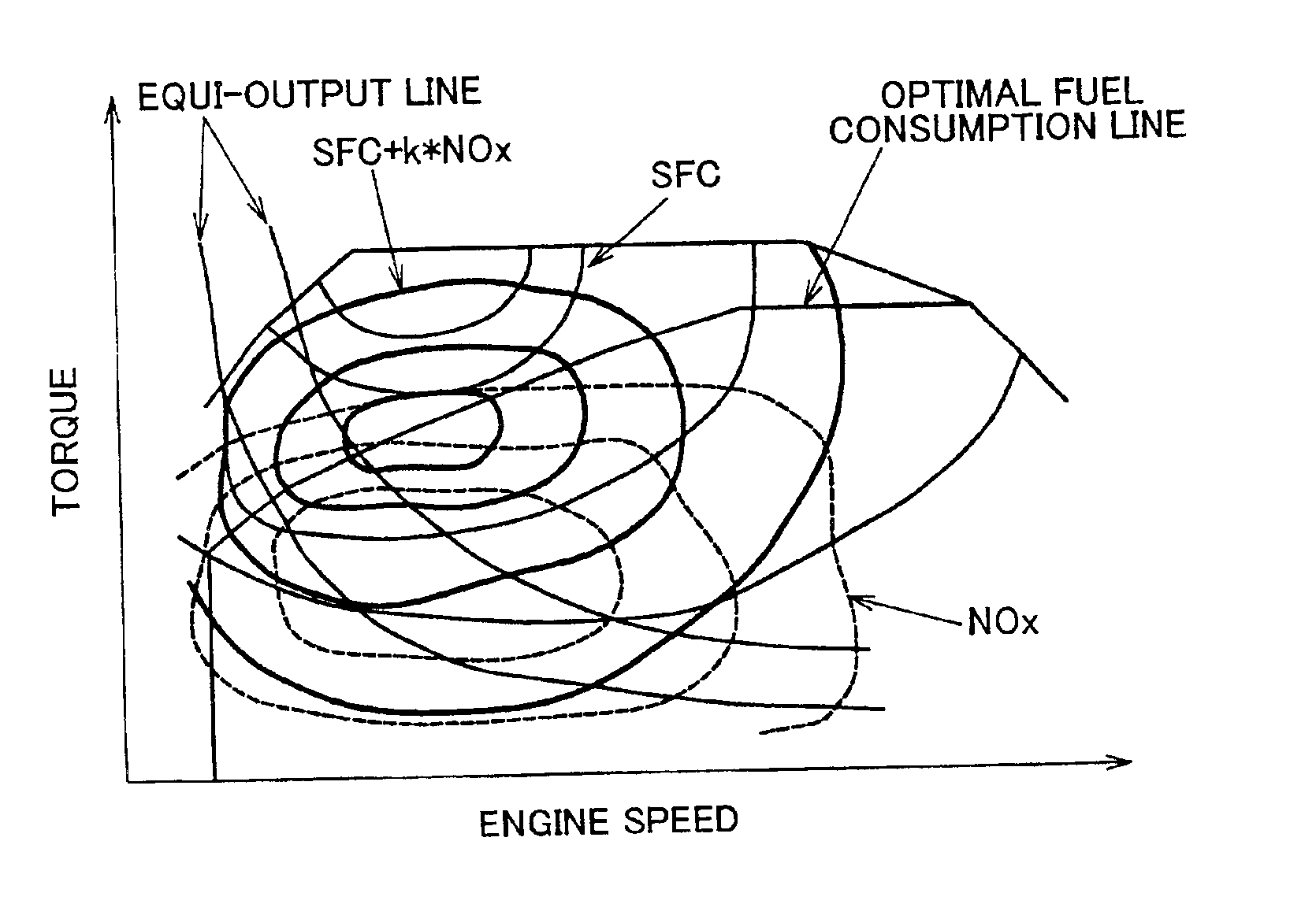
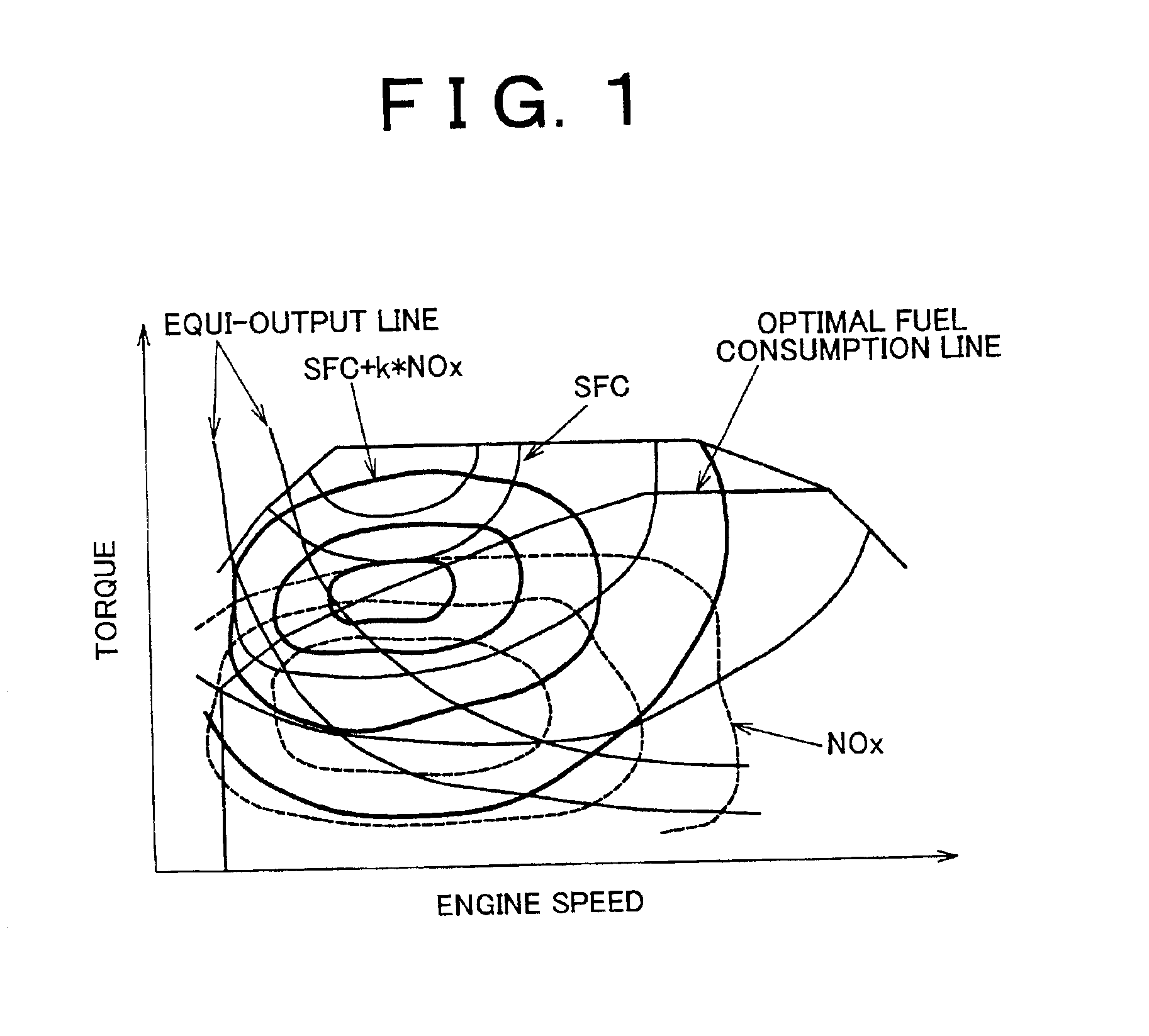
Thus, a fuel consumption characteristic (or fuel economy) and a NOx emission characteristic have a contradictory relationship with each other, which means that an improvement of one of these characteristic results in deterioration of the other characteristic.
Namely, if the amount of one of these emissions is reduced excessively, the amount of the other emission increases significantly.
Although this arrangement gives grounds for selecting a lean-burn operation or a stoichiometric operation on the equi-output line, it is not designed to determine the optimal operating state.
Namely, in the case where the fuel consumption rate and the amount of NOx emission change with the engine speed and the engine torque, the apparatus is not able to determine the optimal operating point that minimizes both the fuel consumption rate and the amount of NOx emission, and is thus not necessarily able to satisfy practical needs or requirements.
Also, in recent years, regulations for emission of environmental pollutants, such as NOx, are getting much stricter, and, as stated in the aforementioned publication, it is getting difficult to comply with the current emission regulations simply by changing operation conditions or combustion conditions of an internal combustion engine.
Since it is undesirable that ammonia be released from vehicles without reacting with other substance, fuel is normally used as the reducing agent.
Although the apparatus as disclosed in the above-identified publication gives grounds for selecting either a lean-burn operation or a stoichiometric operation on the equi-output line, it is not designed to determine the optimal operating state while taking account of the amount of fuel consumed for removing pollutants, such as NOx, in the exhaust gas.
Accordingly, the fuel efficiency or fuel economy is not necessarily optimized when the NOx storage-reduction catalyst is used.
In addition, a so-called emission control device including the filter or the catalyst as mentioned above is not necessarily able to purify exhaust gas without limitation, but its function or activity needs to be restored or recovered.
Nevertheless, effective devices or techniques for achieving both requirements have not been sufficiently developed, nor disclosed in the aforementioned publication.

Method used


Image

  • Control apparatus and method for vehicle having internal combustion engine and continuously variable transmission, and control apparatus and method for internal combustion engine
  • Control apparatus and method for vehicle having internal combustion engine and continuously variable transmission, and control apparatus and method for internal combustion engine
  • Control apparatus and method for vehicle having internal combustion engine and continuously variable transmission, and control apparatus and method for internal combustion engine

Examples


Embodiment Construction

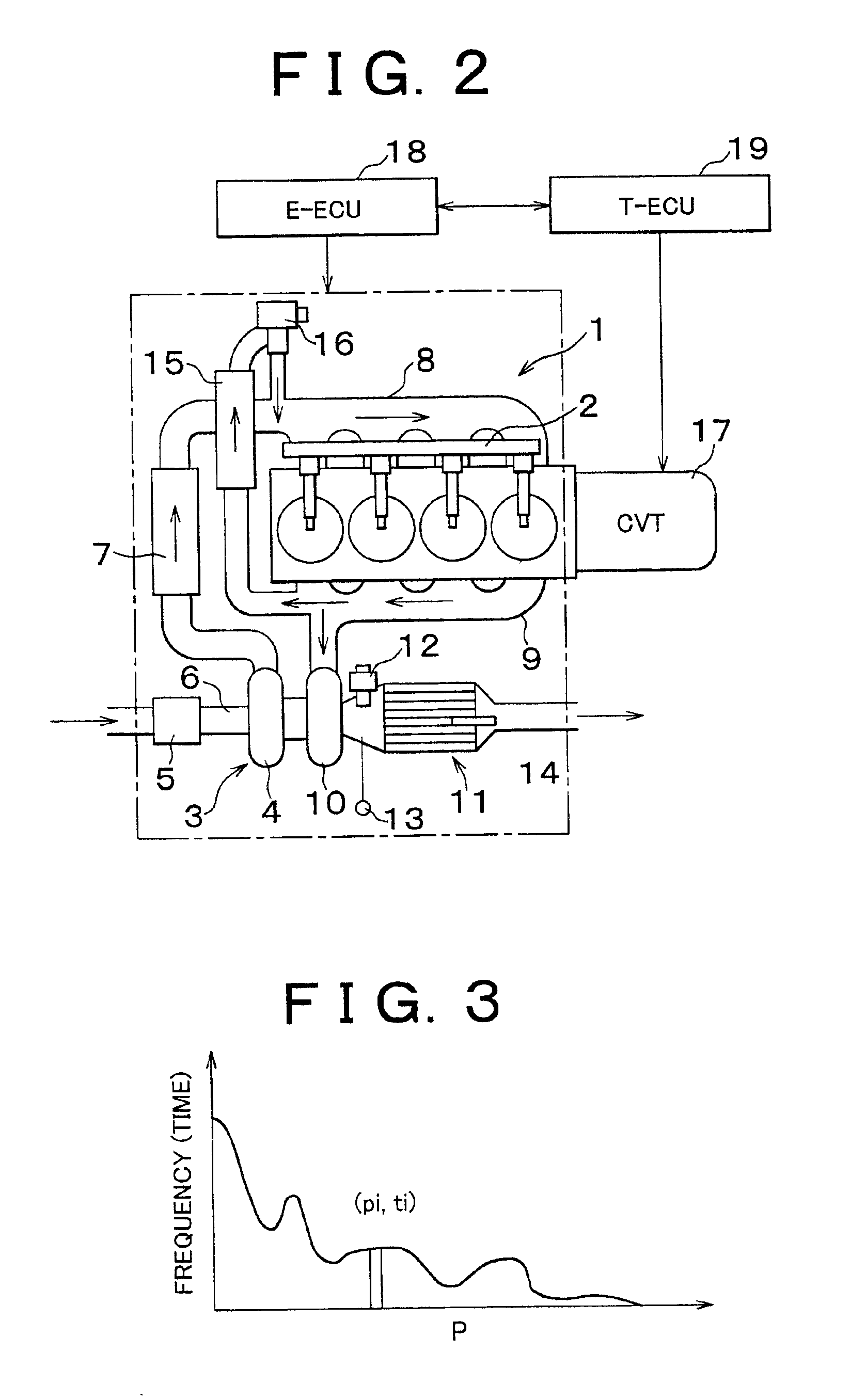
Hereafter, some exemplary embodiments of the invention will be described in detail with reference to the drawings. An internal combustion engine to be controlled by a control apparatus for a vehicle or an engine according to the exemplary embodiments is a power generating device, such as a diesel engine and a gasoline engine, for generating power by burning a fuel. For example, the internal combustion engine is installed on a motor vehicle, such as an automobile, and is primarily used as a power source for running the vehicle. FIG. 2 schematically illustrates an example of a direct-injection type diesel engine 1 (hereafter simply called “engine”) used as a vehicle power source. The engine 1 is of the direct-injection type in which the fuel is injected directly into cylinders, and is provided with an electronically controlled fuel injection system 2 of a common rail type, which permits fuel injection at a high pressure. The electronically controlled fuel injection system 2 of this em...


PUM


Abstract

A control apparatus is provided for a vehicle including an internal combustion engine and a continuously variable transmission capable of controlling an output speed of the engine. A controller of the control apparatus determines a first operating point at which a total fuel consumption amount is minimized as an optimal operating point, such that the total fuel consumption amount is obtained by adding an amount of a fuel consumed by an exhaust purifying device disposed in an exhaust system to an amount of a fuel consumed by the engine for generating a required output. The controller then controls an engine load and also controls a speed ratio of the transmission so that the engine operates at the optimal operating point.

Description

INCORPORATION BY REFERENCEThe disclosures of Japanese Patent Applications No. 2001-101692 filed on Mar. 30, 2001, No. 2001-124998 filed on Apr. 23, 2001, No. 2001-124999 filed on Apr. 23, 2001, each including the specification, drawings and abstract, is incorporated herein by reference in its entirety.BACKGROUND OF THE INVENTION1. Field of the InventionThe invention relates to control apparatus and method for a vehicle having a driving mechanism in which a continuously variable transmission (hereinafter called “CVT”) is coupled to the output side of an internal combustion engine, such as a diesel engine. More particularly, the invention is concerned with control apparatus and method for controlling an output of the internal combustion engine so as to reduce the amount of a pollutant(s) in exhaust gas without deteriorating the fuel economy. The invention also relates to control apparatus and method for an internal combustion engine, such as a diesel engine, and more particularly to c...

Claims


Application Information

Patent Timeline
IPC IPC(8): F02D41/02F02D17/00F02D35/00F02D17/02F02D41/32F02D41/36F02D11/10F01N3/08F02B37/00F02M25/07B60W10/06B60W10/10B60W30/18F02D41/00F02D45/00F16H61/66
CPCB60W10/101B60W30/1882F01N3/0842F02D11/105F02D41/0055F02D41/0087F02D41/0215F02D41/0225F02D41/0235F02D41/0275F02D41/2422F02D41/345F02M25/0702F02M25/0727F16H61/66B60W10/06B60K2741/145Y10T477/663F02B29/0406F02B37/00F02D41/029F02D41/1446F02D2250/18F02D2400/12F02M25/0707F02M25/0738Y02T10/44Y02T10/52Y02T10/54Y02T10/47Y10T477/619Y10T477/623B60W10/04B60W30/1819F02M26/05F02M26/49F02M26/23F02M26/33Y02T10/84Y02T10/40F02D41/02
Inventor ITO, YASUSHI
Owner TOYOTA JIDOSHA KK
Learn More