
Method for testing analog circuits

a technology of analog circuits and circuits, applied in the field of circuit testing, can solve the problems of costly (though optimized) specification tests for fault detection, testing methodologies that resort to costly (but optimized) specification tests, and the cost of such tests

Inactive Publication Date: 2005-03-08
GEORGIA TECH RES CORP
View PDF13 Cites 23 Cited by
  • Summary
  • Abstract
  • Description
  • Claims
  • Application Information

AI Technical Summary

Benefits of technology

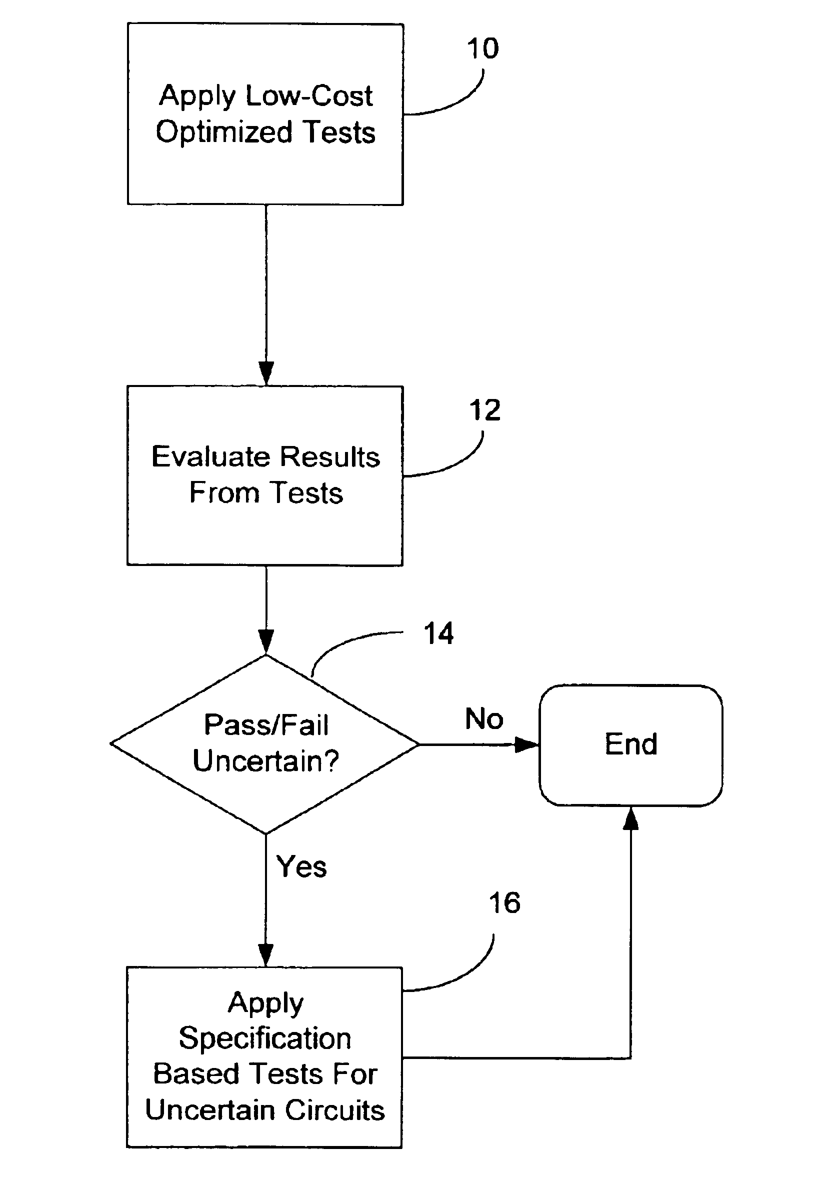
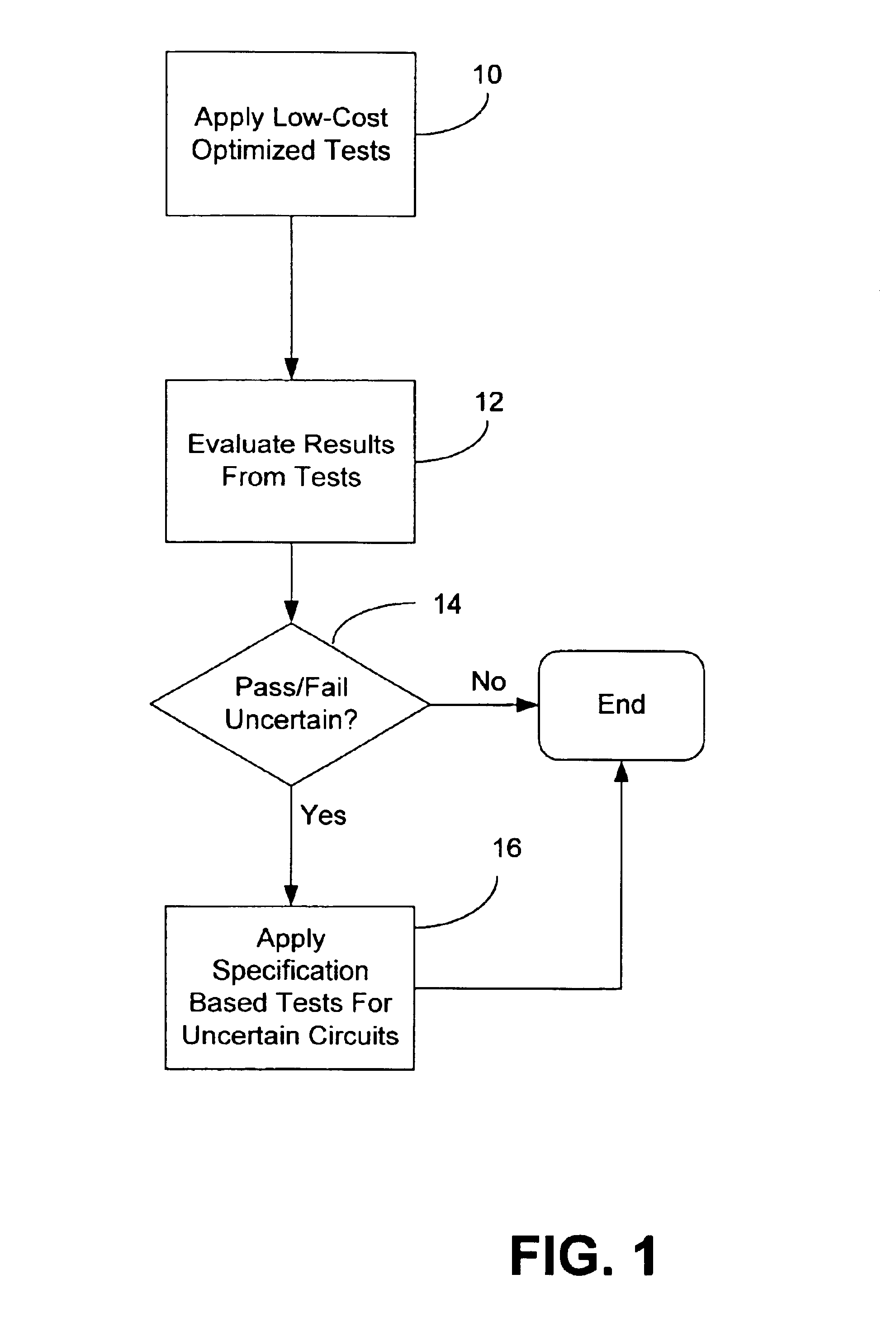
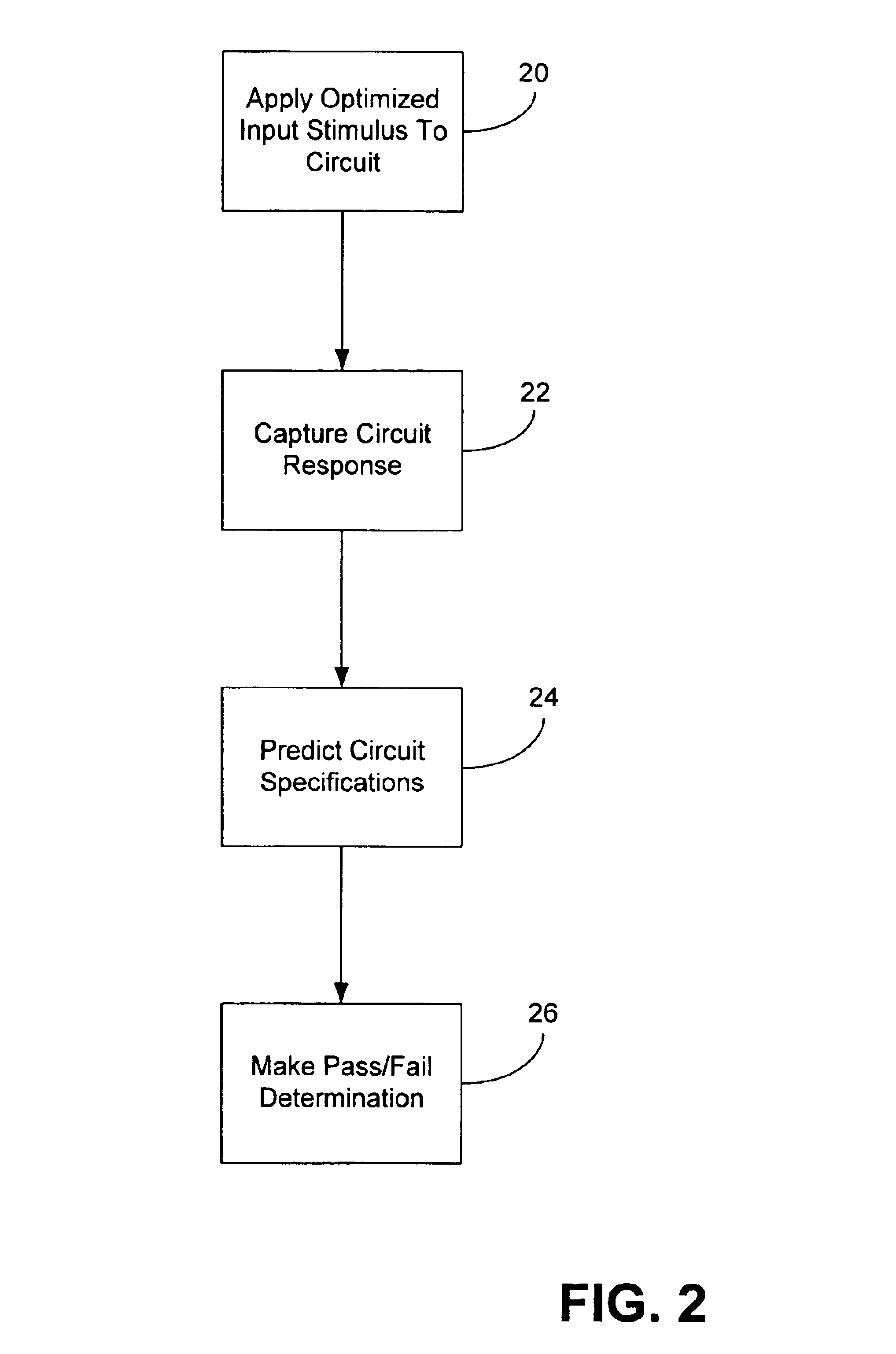
The present disclosure relates to a method for testing a circuit having analog components. The method comprises performing a low-cost optimized test on the circuit by applying an optimized input stimulus to the circuit, capturing the circuit response to the input stimulus applied to the circuit, evaluating the circuit response to predict whether the performance parameters of the circuit satisfies predetermined specifications for the circuit, and making a pass / fail determination for the circuit based upon the evaluation of the circuit response.

Problems solved by technology

Foremost perhaps is the cost associated with such testing.
Testing costs include both the cost of test development as well as the costs associated with conducting the actual manufacturing tests.
Although the tests derived using the above mentioned testing schemes can substitute for the conventional specification tests performed during the final test stage of analog circuits, these test methodologies again resort to costly (although optimized) specification tests for fault detection.

Method used


Image

  • Method for testing analog circuits
  • Method for testing analog circuits
  • Method for testing analog circuits

Examples


example 1

Table 1 provides the performance specifications of an operational amplifier. In the absence of real data from the silicon foundry, it is assumed that the specification failure in this operational amplifier is caused by variations in seven parameters namely, the threshold voltages (Vton Vtop), gate oxide thickness (TOX) aspect ratios ((W / L)n, (W / L)p), bias resistance (Rbias) and compensating capacitor (CC). For the purpose of this example, it is assumed that the test measurement hardware has the capability of measuring small signal voltage gain of the operational amplifier for fault detection with 0.1% accuracy.

TABLE 1Specifications of the Compensated Operational AmplifierPerformanceNumber ofParameterSpecificationMeasurementsBias current<2 mA11F−3 dB frequency>37 KHz2DC gain>49 dB1Phase margin>82°1Gain margin>23 dB3

First, the training set for building the synthesizing function for each of the specification was generated using the algorithm FindTrainSet( ). The voltage gain at a ...

example 2

Now the simulation results on an ITC'97 bench mark circuit, state-variable filter will be discussed. The faults in the state-variable filter were assumed to be due to variations in 16 parameters, seven of them are the process parameters of the operational amplifier and the remaining nine are the values of passive components of the state variable filter. For the state-variable filter, two double-ended specifications and one single ended specification were considered. The performance parameters and the specifications are given in Table 3.

TABLE 3Specification of the State-Variable FilterNumber ofPerformance ParameterSpecificationsMeasurementsCenter Frequency of the Band->750 Hz1Pass Filter (ƒc)<850 Hz4Maximum gain (K)>1.03<1.21Q-factor (Q)>1.011

To test this circuit, transient tests were generated using the methods described herein. To generate a training set for test generation, the two double-ended specifications were decomposed to single-ended specifications to give a total...


PUM


Abstract

The present disclosure relates to a method for testing a circuit having analog components. The method comprises performing a low-cost optimized test on the circuit by applying an optimized input stimulus to the circuit, capturing the circuit response to the input stimulus applied to the circuit, evaluating the circuit response to predict whether the performance parameters of the circuit satisfies predetermined specifications for the circuit, and making a pass / fail determination for the circuit based upon the evaluation of the circuit response.

Description

FIELD OF THE INVENTIONThe present disclosure relates to a method for testing circuits. More particularly, the disclosure relates to a method of testing circuits having analog components, and a method of developing the tests applied to them.BACKGROUND OF THE INVENTIONCurrently, comprehensive and low-cost test methodologies for analog and mixed-signal systems analogous do not exist. Test methodologies for mixed-signal systems are based primarily on the paradigm of measuring the circuit's specifications to determine if they are “good” or “bad”. This method is known as specification based testing. With this method of testing, each specification is measured for each circuit, e.g., an integrated circuit (IC), to ensure that the circuit satisfies all specified parameters.Specification based testing has many drawbacks. Foremost perhaps is the cost associated with such testing. Testing costs include both the cost of test development as well as the costs associated with conducting the actual ...

Claims


Application Information

Patent Timeline
IPC IPC(8): G01R31/01G01R31/3163G01R31/28
CPCG01R31/01G01R31/3163G01R31/2846G01R31/2837
Inventor VARIYAM, PRAMODCHANDRAN N.CHATTERJEC, ABHIJIT
Owner GEORGIA TECH RES CORP
Learn More