Certain aspects of the present invention may overcome one or more aforementioned drawbacks of the previous art and / or advance the state-of-the-art of
optical power control devices and fabrication thereof, and in addition may meet one or more of the following objects:To provide cylindrical
processing methods and apparatus for
processing optical media;To provide cylindrical
processing methods and apparatus wherein rings and partial rings may be machined onto an
optical fiber;To provide cylindrical processing methods and apparatus for producing a fiber-ring optical resonator;To provide delocalized-optical-mode suppressors for substantially eliminating undesirable
optical resonance of the fiber-ring and / or optical fiber;To provide cylindrical processing methods and apparatus for producing fiber-taper positioner on an optical fiber;To provide a resonant
optical power control device that may be reliably and reproducibly fabricated;To provide a resonant
optical power control device that may be reliably and reproducibly fabricated without resorting to active alignment procedures;To provide a resonant optical
power control device with low
insertion loss;To provide a resonant optical
power control device with a
free spectral range suitable for use in WDM applications;To provide a resonant optical
power control device wherein an optical wave propagating through an optical fiber is coupled to a resonant circumferential-mode optical resonator;To provide a method for fabricating a circumferential-mode optical resonator on the circumference of an optical fiber, thereby providing a fiber-ring resonator;To provide a method for fabricating a circumferential-mode optical resonator on the circumference of an optical fiber by altering a circumferential
optical pathlength (by altering
diameter,
refractive index,
chemical composition, density, and so on) of a transverse resonator segment of the optical fiber;To provide a method for fabricating an optical power control device wherein the optical fiber and the circumferential-mode resonator are positioned and secured within alignment grooves on an alignment substrate;To provide a method for fabricating an optical power control device wherein the circumferential-mode resonator is provided with an alignment groove and / or
flange for passive alignment within an alignment grooves on an alignment substrate;To provide a method for fabricating an optical power control device wherein the optical fiber has a fiber taper segment for optically
coupling to the circumferential-mode resonator;To provide a method for fabricating an optical power control device wherein the optical fiber may be heated and pulled to form a fiber taper segment within an alignment groove on an alignment substrate; andTo provide a method for fabricating an optical power control device wherein a fiber taper segment may be received by a fiber-taper positioner provided on or near the circumferential-mode optical resonator;To provide a method for fabricating an optical power control device wherein a fiber taper segment may be wrapped around a circumferential-mode optical resonator;To provide a method for fabricating a resonant
optical filter by providing a second fiber-optic waveguide coupled to the circumferential-mode optical resonator; andTo provide a method for fabricating a resonant
optical modulator by providing a modulator for controlling optical properties of the circumferential-mode resonator.
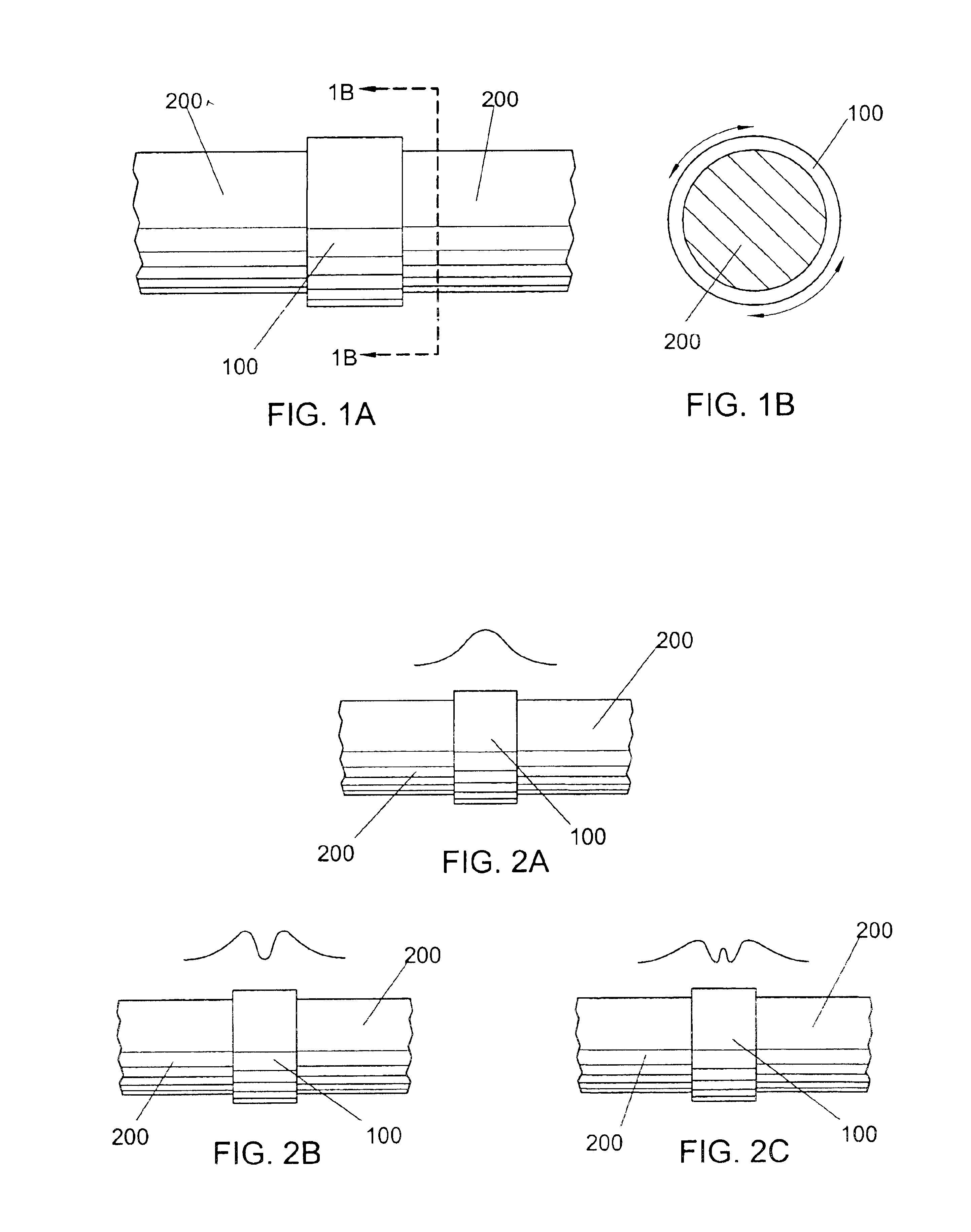
One or more of the foregoing objects may be achieved in the present invention by a method for fabricating a circumferential-mode optical resonator on an optical fiber, comprising the step of generating a differential of a circumferential
optical pathlength (by altering
diameter, density,
refractive index,
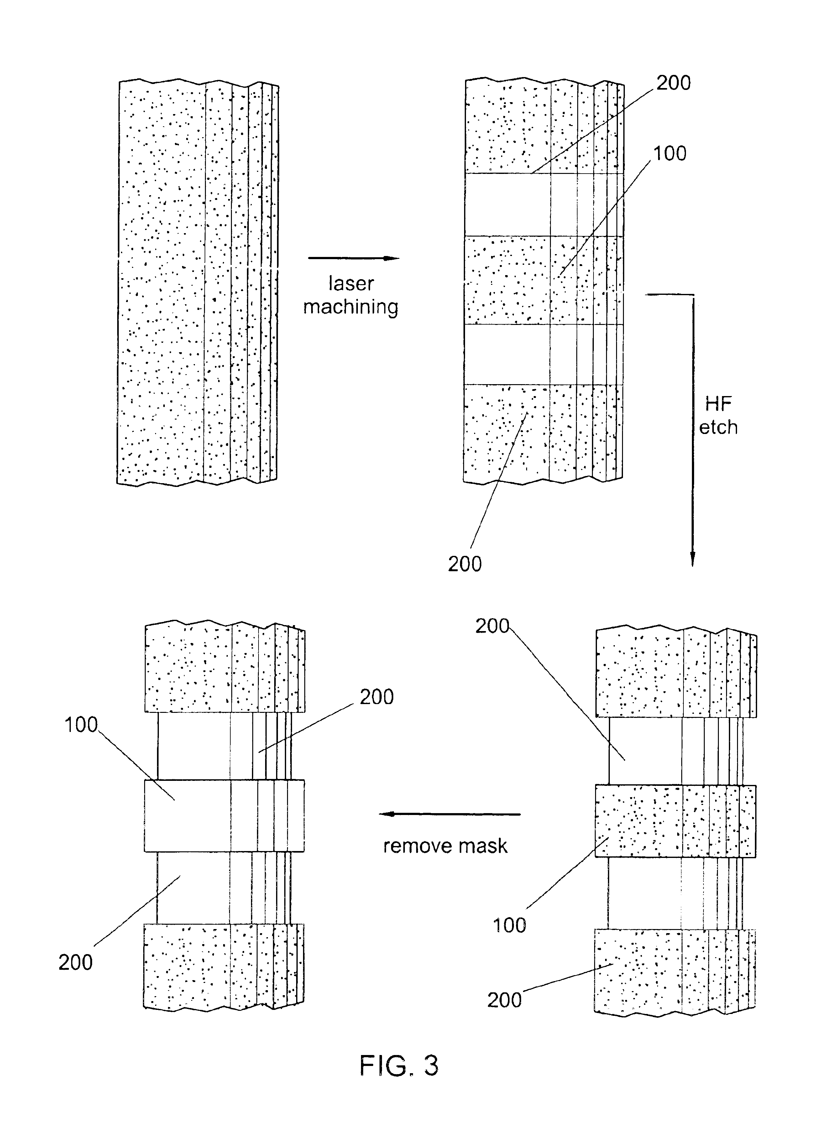
chemical composition, and so forth) of a transverse resonator fiber segment relative to the longitudinally adjacent fiber segments. The resonator fiber segment may therefore substantially confine a circumferential optical mode propagating around the resonator fiber segment circumference at least partially within the resonator fiber segment. Specialized techniques for spatially selectively generating the differential may include masking /
etching, masking / deposition,
laser machining,
laser patterning, combinations thereof, and / or functional equivalents thereof. The circumferential-mode resonator may be further provided with an alignment
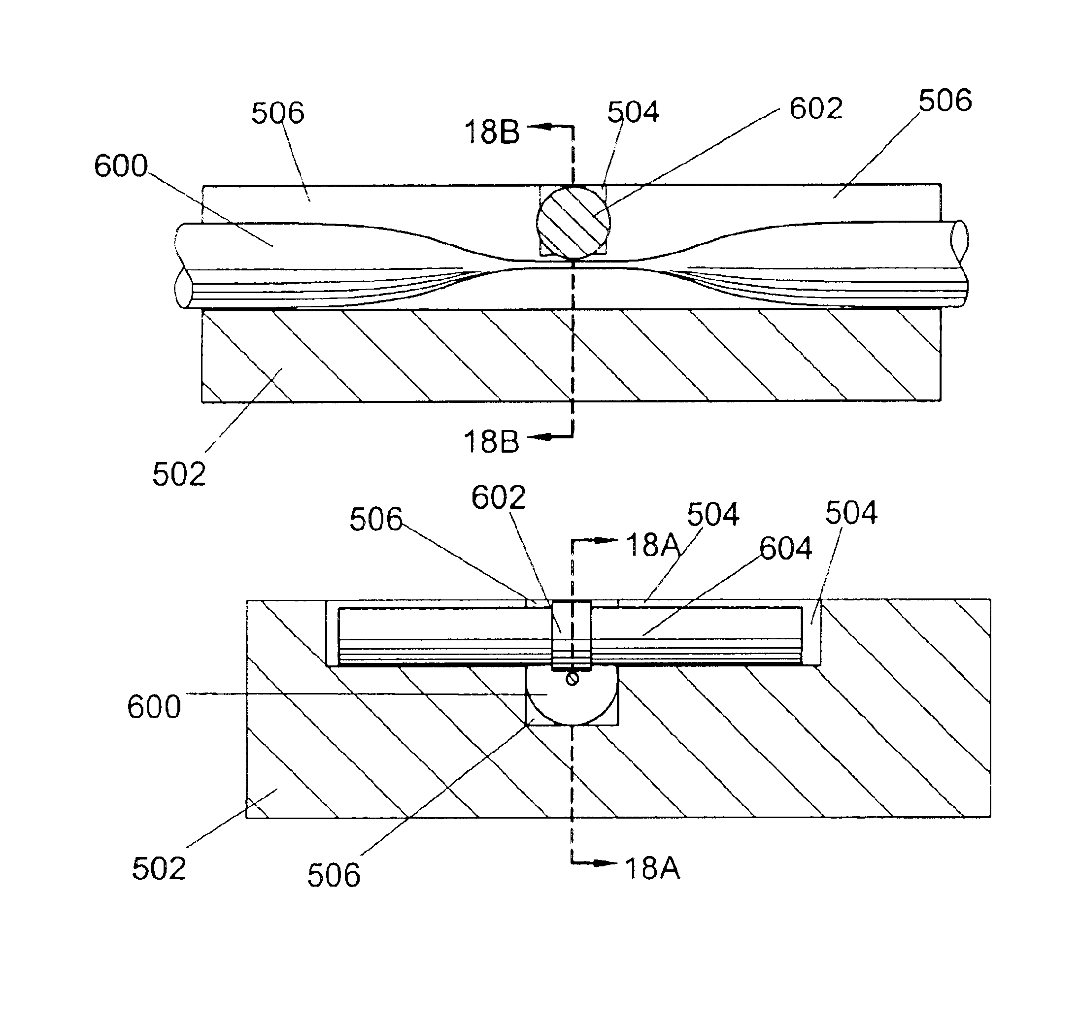
flange and / or groove for enabling passive positioning of the circumferential-mode resonator within an alignment groove of an alignment substrate. A preferred method for fabricating an optical power control device according to the present invention comprises the steps of: 1) fabricating a circumferential-mode resonator as described herein; 2) heating and pulling a transmission optical fiber to form a fiber taper segment; 3) fabricating an alignment substrate having a resonator-alignment groove and a fiber alignment groove thereon; 4) positioning and securing the fiber taper segment within the fiber-alignment groove; 5) positioning and securing the circumferential-mode resonator within the resonator-alignment groove so that the circumferential-mode resonator and the fiber taper segment are optically coupled (through close proximity and / or direct contact between them). The alignment grooves are fabricated at the correct depths and positions and with corresponding alignment grooves and / or flanges to enable the
optical coupling without extensive active alignment procedures. Additional alignment structures and positioners may be provided to facilitate and adjust
optical coupling of the circumferential-mode resonator and the fiber-optic taper. In a resonant
optical filter, a second fiber-optic taper may be coupled to the resonator. In a resonant
optical modulator, a modulator may be provided as an integral component of the circumferential-mode resonator, provided directly on the circumferential-mode resonator, or as a separate
assembly positioned on and secured with respect to the alignment substrate. The modulator enables control of the optical properties of the circumferential-mode resonator, which in turn enables control of the optical power transmitted through the fiber taper segment of the transmission optical fiber.
