
Method and device for cleaning high-voltage carrying installation component parts

a cleaning method and installation technology, applied in the direction of cleaning process and apparatus, water supply installation, gas/liquid distribution and storage, etc., can solve the problems of reducing the isolator's isolator's isolator effect, contaminated components in electric power supply facilities, and contaminated components in transformers and switchboard stations, so as to ensure the safety of the installation and the personal protection of the cleaning personnel, and improve the effect of safety

Inactive Publication Date: 2005-03-08
PREISING PAUL ERIC
View PDF9 Cites 43 Cited by
  • Summary
  • Abstract
  • Description
  • Claims
  • Application Information

AI Technical Summary

Benefits of technology

Employing the inventive cleaning method and the corresponding device, for the first time, it is possible to clean installation component parts with applied high-voltage without endangering the safety of the cleaning personnel and without employing cleaning agents that leave behind solid or liquid residues. The cleaning quality is adapted to the requirements of electric installations: fatty matters, environmental dirt and damages due to fire accidents can be completely removed without damaging the component parts of the installation.
Modifications of the inventive cleaning method and the corresponding device provide an additional monitoring of the humidity of pressure gas and / or ambient air. Thus, the personal protection and the safety of the installation is always guaranteed even at extremely unfavorable conditions such as high humidity or a shortage of dry-ice particles. An other modification improves safety by monitoring the isolation power of the distancing means. A further modification of the inventive method and the inventive device proposes a removal of the loosened dirt particles by suction. Thus, the cleaning process will become easier and faster.

Problems solved by technology

Components in electric power supply facilities as e.g. components in transformer and switchboard stations are contaminated by dirt due to the influence of their operation, their environment and special events (such as e.g. fires).
For example, even if they have only a low conductivity, electrically conducting adherents at the surface of a ceramic isolator can decrease the isolating effect of the isolator.
In extreme cases the can give rise to an electric arc and so at least for a short time cause an operation breakdown.
Consequences of such operation breakdowns range from short-time power interruptions to fires in an installation.
At least during the cleaning process this requires an operation shut-down which is economically disadvantageous and, moreover, often causes technical problems.
The economic damage that electric supply and industry companies suffer due to the shut-down time required for cleaning high-voltage installations is important and would justify a considerable additional expenditure for the cleaning method in order to avoid shut-down.
Cleaning methods employing chemical cleaning agents usually leave behind liquid or solid residues that can be a risk to the operation safety of the installation depending on the nature of the residues.
The residues themselves can play the role of a kind of contamination and can influence the isolation effect of component parts or they can develop corrosion at component parts.
Thus, cleaning agents themselves must usually be expensively removed.
This results in complicated and time-consuming cleaning processes.
However, their cleaning often is less effective especially when oils and fatty matters are involved.
Such wet-cleaning methods have severe drawbacks: on the one the high humidity can develop corrosion at the component parts and on the other hand dirty and thus contaminated waste water arises which must be disposed of or reprocessed.
Without additional detergents or solvents it is only partly possible to remove fatty or oily residues.
Thus, cleaning at operational voltage without exposing the cleaning personnel to danger is only possible in a low-voltage range (i.e. the range below 1 kV).
Most of these methods (more precisely, most blast particle media) exhibit a strong abrasive effect that impairs the surface of the component parts to be cleaned.
The resulting thermal stress weakens the bondage between the dirt or contamination coating and the surface of the component parts to be cleaned.
The contamination's freezing and embrittlement also reduces its adhesive strength.
Unfortunately, the instruments and methods for cleaning with dry-ice particles as, e.g., they are known from the previously mentioned documents cannot directly be employed for cleaning high-voltage installations that are not powered down since neither the personal protection of the personnel nor the safety of the instrument against high-voltage is provided.
So, the cleaning workers must approach the installation to be cleaned to much, so that the danger of a high-voltage flashover arises.
Moreover, two important problems that can arise in principle must be taken into consideration, namely condensing atmospheric humidity that creates an additional conductivity and the effects of the removed dirt particles.
Especially for indoor installations, this could have fatal effects since their isolation distances have not been designed for condensing humidity.
Thus, this could give rise to flashovers and electric arcs which would not only endanger the installation safety but also the cleaning personnel's safety.
Since the minimum safety distances have been designed for normal installation operation but electric arcs could bridge a wider range, even when working at distance cleaning personnel would run a considerable risk of being hurt especially by scalds.
An other point of danger is the fact, that possibly the pressure air transporting the carbon-ice particles contains humidity that could induce a certain conductivity, thus, endangering the cleaning personnel as well as the cleaning device.
The second problem are the removed dirt particles.
What would be no or nearly no problem in a 3 kV installation and only a slight problem in a 30 kV installation could grow to a deadly danger in a 300 kV installation.

Method used


Image

  • Method and device for cleaning high-voltage carrying installation component parts
  • Method and device for cleaning high-voltage carrying installation component parts
  • Method and device for cleaning high-voltage carrying installation component parts

Examples


Embodiment Construction

The figures are not true to scale for clarity reasons.

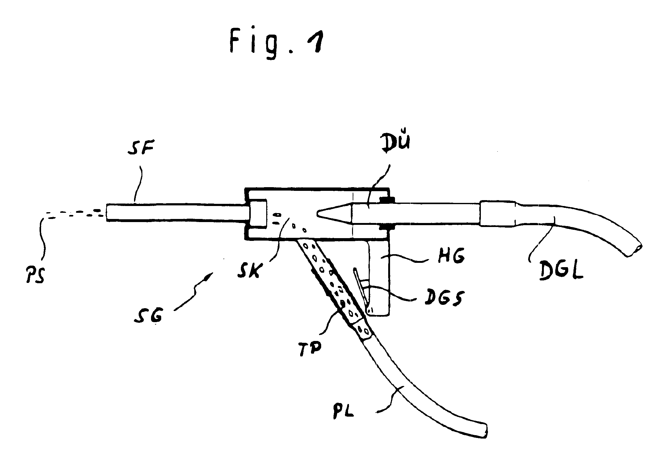
The heart of each device for cleaning with dry-ice particles is the jet generator that produces the cleaning two-phase jet consisting of the pressure gas as carrier medium and the carried dry-ice particles. Following, it is simply designated as particle jet.

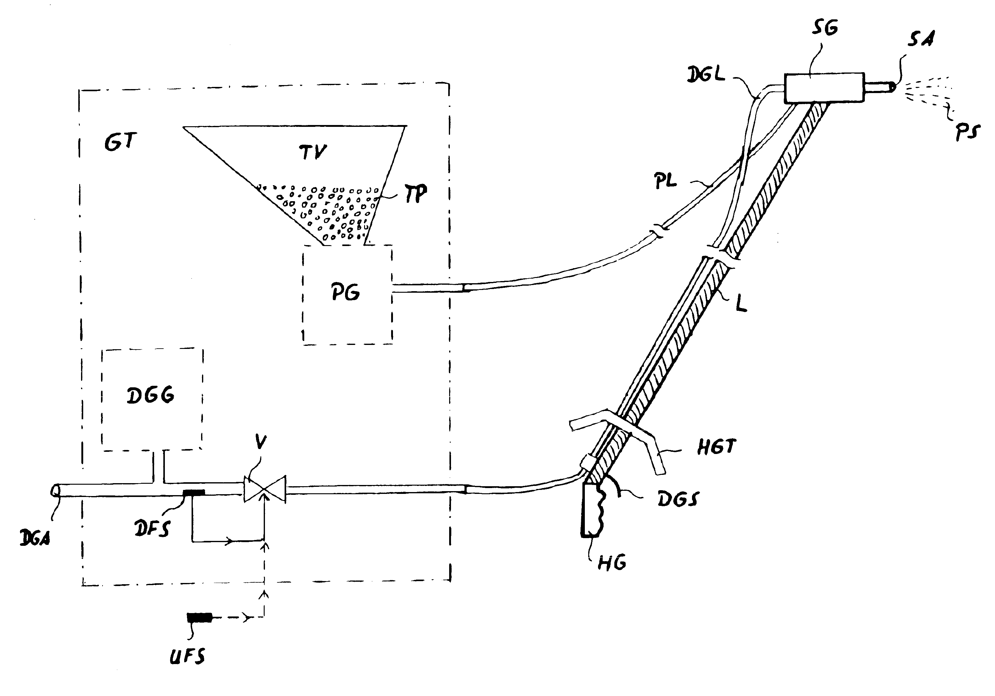
FIG. 1 depicts a jet generator as it is known from prior art. It can be employed as a component of the inventive device. A pressure gas is provided via a pressure-gas line DGL (a tube, e.g.), dry-ice particles TP are provided via a particle line PL. Through a nozzle DÜ the pressure gas emerges into the jet chamber SK. The thereby highly increased velocity of flow generates a partial vacuum in the jet chamber SK. Due to said vacuum dry-ice particles TP are sucked via the particle line PL, dragged into the pressure gas stream and carried by it further along. Then, the particle jet PS consisting of pressure gas as carrier medium and dry-ice particles leaves through the jet emitti...


PUM

PropertyMeasurementUnit
voltageaaaaaaaaaa
sublimation pointaaaaaaaaaa
lengthaaaaaaaaaa

Abstract

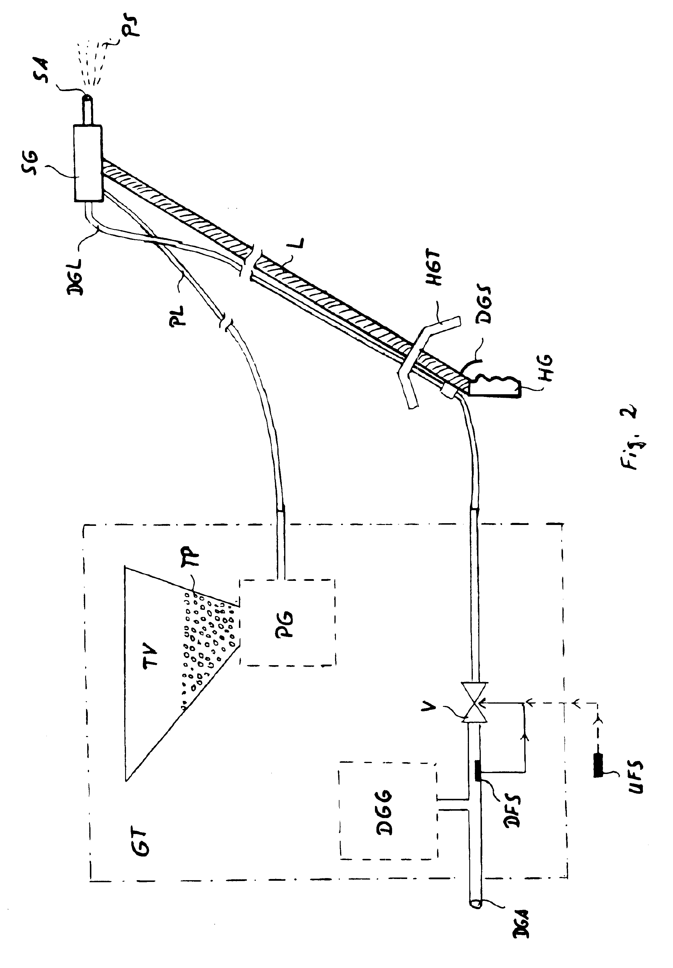
A cleaning method and a corresponding cleaning device offer adequate protection to individuals, devices and installations, for cleaning component parts of installations that carry an electrical high-voltage and which are not disconnected during cleaning. Towards this end, the component parts to be cleaned are subjected to the action of a two-phase particle stream (PS) consisting of a compressed gas (DGA) serving as a carrier medium and of carbon dioxide ice particles (TP) carried therein. Possible superficial accumulations of dirt are removed from the component parts by way of low-temperature embrittlement and by the kinetic energy of the impacting carbon dioxide particles. The carbon dioxide ice particles themselves sublimate without leaving residues. A sufficiently safe distance of cleaning personnel from the high-voltage carrying insulation component parts is ensured by the provision of an electrically insulating distance mechanism (L, SFR) that is provided approximately in the form of a lance (L) or of a stream guided tube (SFR). A further increase in protection is offered by monitoring the quantity of moisture of compressed gas and / or ambient air, whereby the cleaning device is immediately shut off when predetermined limiting values are exceeded.

Description

BACKGROUND OF THE INVENTIONThe present invention relates to a cleaning method and a cleaning device for installation component parts that carry an electrical high-voltage.Components in electric power supply facilities as e.g. components in transformer and switchboard stations are contaminated by dirt due to the influence of their operation, their environment and special events (such as e.g. fires). The dirt and the adherent contamination are of various nature. The possible range of dirt and contamination starts at slightly adherent, powdery, inorganic or organic dirt and extends over oils, fatty matters, liquid films and so-called biological films consisting of fungi and algae to nearly burnt-in residues consisting of metals, metal oxides and carbon which arise due to spark discharges and electric arcs.Component parts of such facilities must be cleaned from time to time in order to maintain reliability of operation of the installations. For example, even if they have only a low cond...

Claims


Application Information

Patent Timeline
Patent Type & Authority Patents(United States)
IPC IPC(8): B24C5/02B24C5/00B24C1/00
CPCB24C1/003B24C5/02B24C3/322B24C1/086Y10T137/0352
Inventor PREISING, PAUL-ERIC
Owner PREISING PAUL ERIC
Learn More