
Back light unit including a diffuser with various diffusion effects

a back light unit and diffuser technology, applied in the direction of instruments, discharge tubes, luminescnet screens, etc., can solve problems such as deteriorating display performan

Inactive Publication Date: 2005-03-01
INNOLUX CORP
View PDF7 Cites 101 Cited by
  • Summary
  • Abstract
  • Description
  • Claims
  • Application Information

AI Technical Summary

Benefits of technology

It is therefore a primary objective of the claimed invention to provide a back light unit with a diffuser which has diffusing effects corresponding to the shapes and positions of the light tubes so as to solve the aforementioned problem.
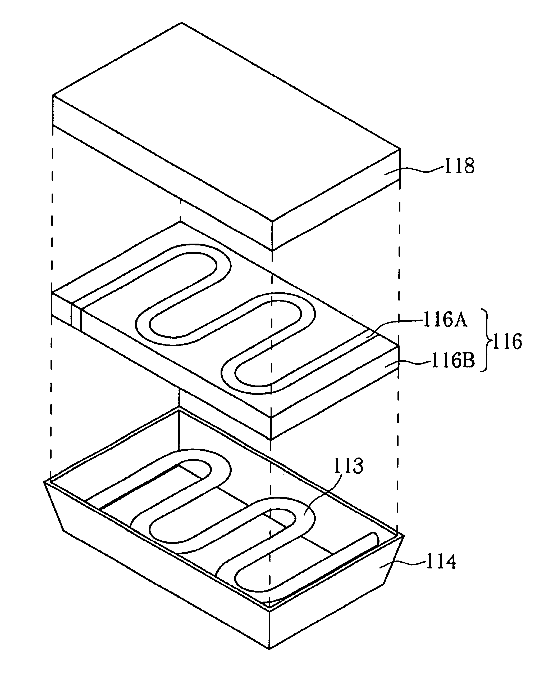
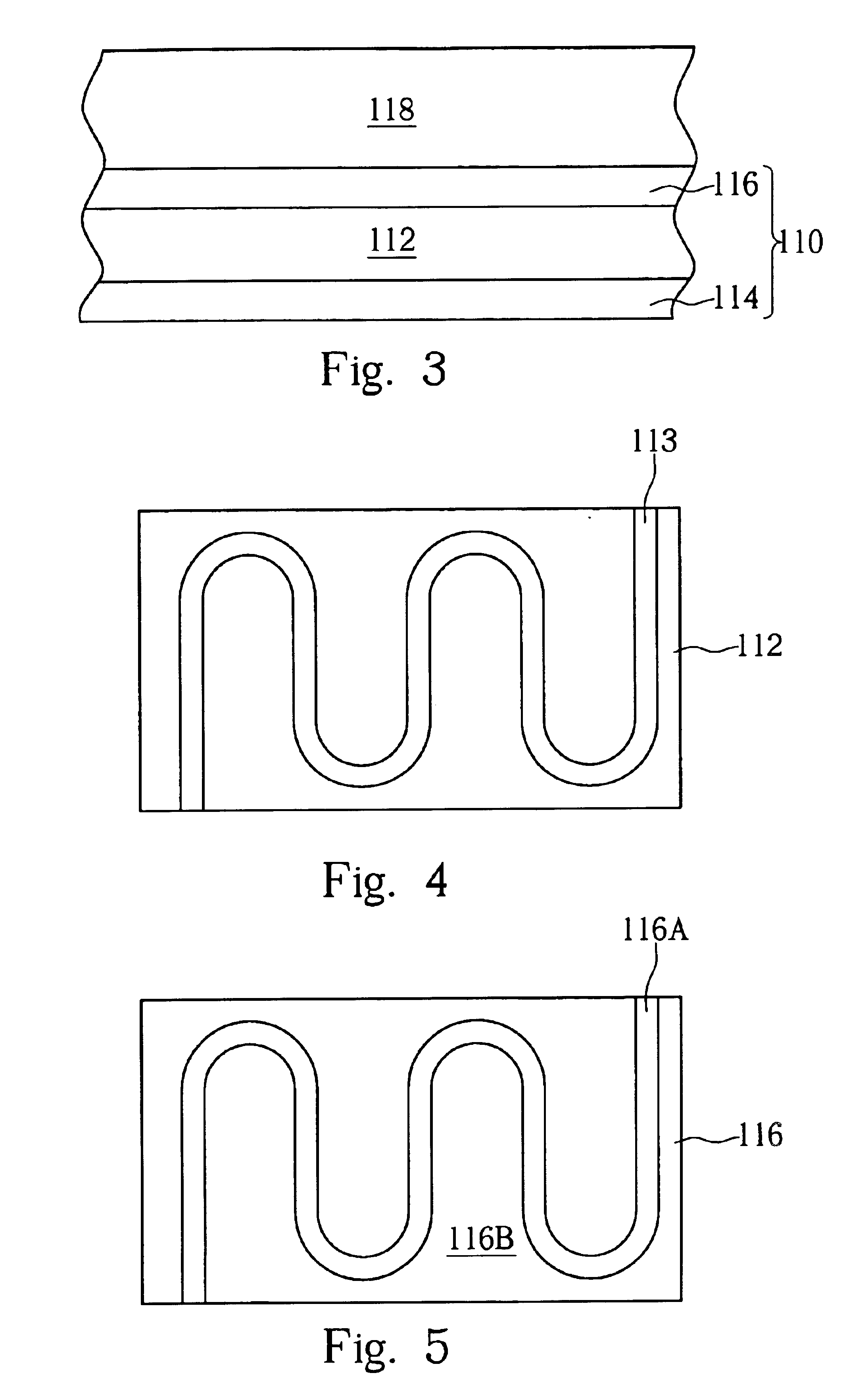
It is an advantage of the claimed invention that the back light unit comprises a diffuser composed of liquid crystal molecules and polymers. The diffuser has a greater scattering effect in the region closer to the tube so as to provide light beams with a better uniformity to the display panel.

Problems solved by technology

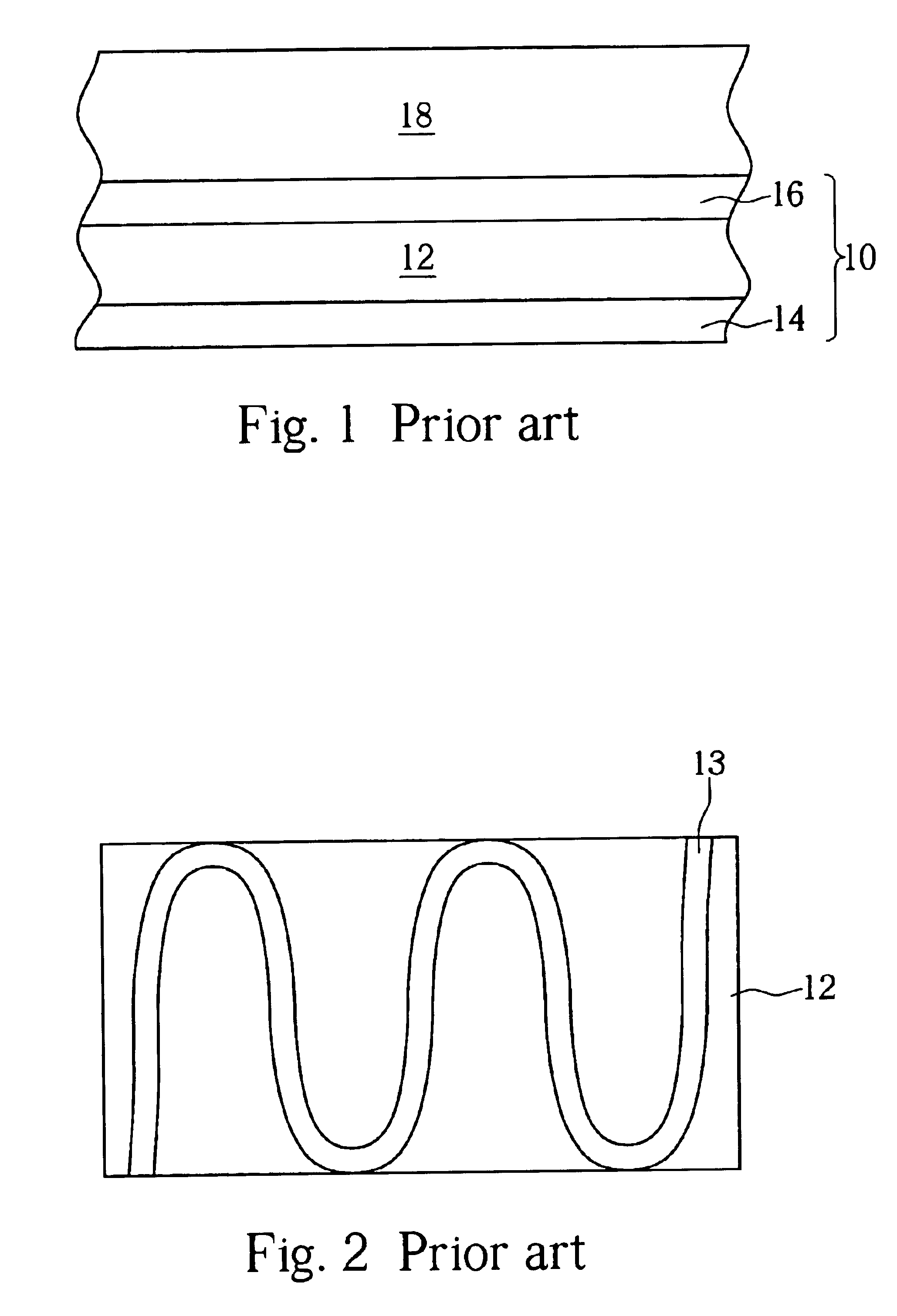
However, when the back light unit 10 outputs light beams with a low luminous intensity or when the screen is almost dark, an obvious highlight region, which has a shape similar to the shape of the light tubes 13, is always shown on the display panel 18 and therefore the display performance is deteriorated.

Method used


Image

  • Back light unit including a diffuser with various diffusion effects
  • Back light unit including a diffuser with various diffusion effects
  • Back light unit including a diffuser with various diffusion effects

Examples


Embodiment Construction

The present invention focuses on a diffuser structure of a back light unit. The remaining structure of the back light unit of the present invention is similar to the conventional back light unit 10, and will not be explained again fully. Please refer to FIG. 3 of a cross=sectional diagram of a back light unit 110 according to the present invention. The back light unit 110 is disposed under a display panel 118 for providing light source to the display panel 118. The back light unit 110 comprises a light source generator 112 for generating light beams and a diffuser 116 disposed on the light source generator 112. The diffuser 116 is composed of liquid crystal molecules and polymers. Since the refraction of the liquid crystal molecules and polymers is anisotropic, when the light beams generated from the light source generator 112 pass through the diffuser 116, the light beams will be refracted by the diffuser 116 so that light beams with a better uniformity can be provided to the displ...


PUM

PropertyMeasurementUnit
sizeaaaaaaaaaa
sizesaaaaaaaaaa
electric fieldaaaaaaaaaa

Abstract

A backlight unit is disposed beneath a display panel. The backlight unit includes an illumination means, which is used to provide a light source, and a diffuser positioned between the illumination means and the display panel, which is used to scatter the light generated by the illumination means. The diffuser, which is composed of liquid crystal particles and polymer, has a plurality of regions. The region thatis closer to the illumination means has greater scattering effect. In addition, the region with the greatest scattering effect has a shape corresponding to the illumination means.

Description

BACKGROUND OF INVENTION1. Field of the InventionThe present invention relates to a back light unit, and more particularly, to a diffuser of a back light unit.2. Description of the Prior ArtAs manufacturing costs decrease and quality improves, liquid crystal displays are widely applied to different kinds of products such as notebooks, personal digital assistants (PDAs), mobile phones, clocks, and so on. Since the liquid crystal displays are passive luminous devices, a back light unit is required for the LCD devices to meet the requirements of night vision and full color imagery.Basically, the back light unit, which is disposed under the display panel, comprises a luminous means and a diffuser for generating light beams and scattering the light beams uniformly to the display panel so as to produce image on the display panel in advance. According to the position of the luminous means, the back light units are divided into several types, such as the vertical back light unit, in which th...

Claims


Application Information

Patent Timeline
Patent Type & Authority Patents(United States)
IPC IPC(8): G02F1/1335G02F1/1334G02F1/13G02F1/13357
CPCG02F1/1334G02F1/133611G02F1/133606
Inventor WEI, CHUNG-KUANG
Owner INNOLUX CORP
Learn More