
Anti-Strokes Raman fiber laser achieving multi-wavelength output

A fiber laser and multi-wavelength technology, applied in the direction of laser scattering effect, the structure/shape of the active medium, etc., can solve the problems of non-adjustable wavelength, no short laser Raman fiber laser, etc., and achieve the effect that the phase matching condition is easy to meet

Active Publication Date: 2013-06-12
NAT UNIV OF DEFENSE TECH
View PDF4 Cites 14 Cited by
  • Summary
  • Abstract
  • Description
  • Claims
  • Application Information

AI Technical Summary

Problems solved by technology

[0008] 1) The wavelengths generated by existing Raman fiber lasers are all realized by Stokes light generated by stimulated Raman scattering, that is, the wavelengths of the obtained light are all greater than the wavelength of the pump light source. Raman Fiber Lasers with Shorter Pump Wavelength Laser Output
[0009] 2) When the wavelength of the pump light is determined, the wavelengths produced by the Raman fiber lasers designed in background technology 1 and background technology 2 are not adjustable; although the Raman fiber lasers in background technology 3 can realize the tunable output wavelength , but the tuned wavelengths are all near the first-order Stokes light, and the output bandwidth is only tens of nanometers
[0010] To sum up, the existing lasers so far cannot meet the requirements of making the output wavelength smaller than the pump wavelength, and making the output wavelength adjustable and broadband

Method used


Image

  • Anti-Strokes Raman fiber laser achieving multi-wavelength output
  • Anti-Strokes Raman fiber laser achieving multi-wavelength output
  • Anti-Strokes Raman fiber laser achieving multi-wavelength output

Examples


Embodiment Construction

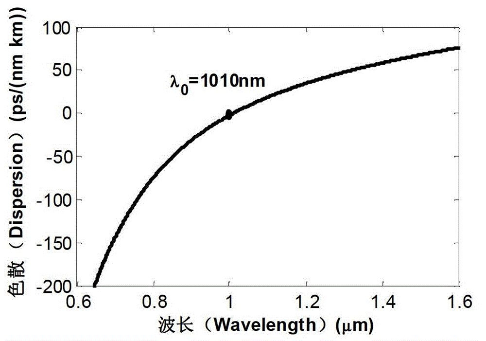
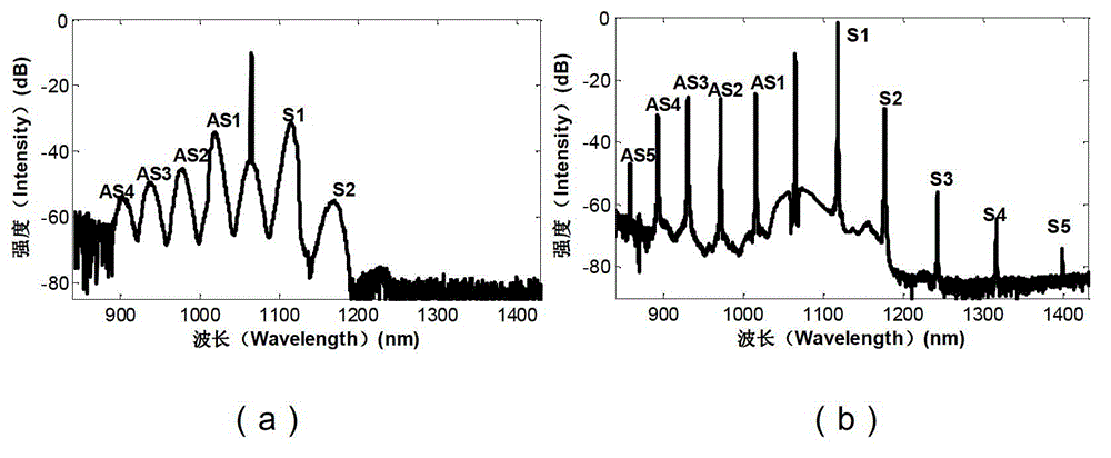
[0029] figure 1 It is a structural representation of the present invention. The invention consists of a pulse light source 1, a continuous light source 2, a wavelength division multiplexer WDM3, a high reflection grating 4, an optical fiber 6, a low reflection grating 5 and a filter 7. Wherein the pulse light source 1 and the continuous light source 2 are connected to the two input arms of the wavelength division multiplexer 3 through a single-mode fiber, and the output arm of the wavelength division multiplexer 3 is connected to the high reflection grating 4 through a single mode fiber, and the high reflection grating 4 It is connected to the optical fiber 6, the other end of the optical fiber 6 is connected to the low reflection grating 5 through a single-mode fiber, and the output end of the low reflection grating 5 is connected to the filter 7 through a single-mode fiber.

[0030] National Defense University Press figure 1A multi-wavelength output anti-Stokes Raman fiber...


PUM


Abstract

The invention discloses an anti-Strokes Raman fiber laser achieving multi-wavelength output and aims at providing a laser of which an output wavelength is adjustable and the output wavelength is smaller than a pump wavelength. The fiber laser is composed of a pulse light source, a continuous light source, a wavelength division multiplexer, a high raster, an optical fiber, a low raster and a filter. The central wavelength of the output light of the pulse light source is located at n stage Raman Strokes wavelength of the obtained light wavelength, the output light wavelength of the continuous light source is located at a first stage Raman Strokes wavelength of the output light wavelength of the pulse light source, a zero-dispersion wavelength of the optical fiber is located near the output light wavelength of the pulse light source, the central wavelength of the high raster and the central wavelength of the low raster are equal to the obtained laser wavelength, the input arm working wavelength of the wavelength division multiplexer is respectively equal to the central wavelength of the pulse light source and the central wavelength of the continuous light source, and the central wavelength of the filter is equal to the obtained light wavelength. The anti-Strokes Raman fiber laser is simple in structure, adjustable in the light wavelength and can output a laser shorter than the pump wavelength.

Description

technical field [0001] The invention belongs to the field of Raman fiber lasers, in particular to a multi-wavelength anti-Stokes Raman fiber laser capable of generating laser light shorter than the pumping wavelength. Background technique [0002] Since the light-emitting mechanism of the laser is different from that of ordinary light sources, the output laser has some outstanding characteristics, namely, good directivity, high brightness, good monochromaticity and coherence. These characteristics of it have played a unique role in all aspects of modern science and technology, and have spread across the fields of industry, military, communications, medicine and scientific research. In order to meet different needs, many different types of lasers have been invented successively, including gas lasers (such as helium-neon lasers, CO 2 Lasers, etc.), solid-state lasers (such as yttrium aluminum garnet lasers), semiconductor lasers (such as GaAs), etc. The output wavelength of ...

Claims


Application Information

Patent Timeline
Patent Type & Authority Applications(China)
IPC IPC(8): H01S3/067H01S3/30
Inventor 李荧侯静冷进勇王文亮姜宗福
Owner NAT UNIV OF DEFENSE TECH
Learn More