
Providing current to compensate for spurious current while receiving signals through a line

a technology of spurious current and receiving signal, which is applied in the direction of optical radiation measurement, radiation control devices, instruments, etc., can solve the problems of spurious current problem, undesired photocurrent on certain other nodes, etc., and achieve the effect of preventing bright light effects

Inactive Publication Date: 2005-03-01
APTINA IMAGING CORP
View PDF15 Cites 0 Cited by
  • Summary
  • Abstract
  • Description
  • Claims
  • Application Information

AI Technical Summary

Benefits of technology

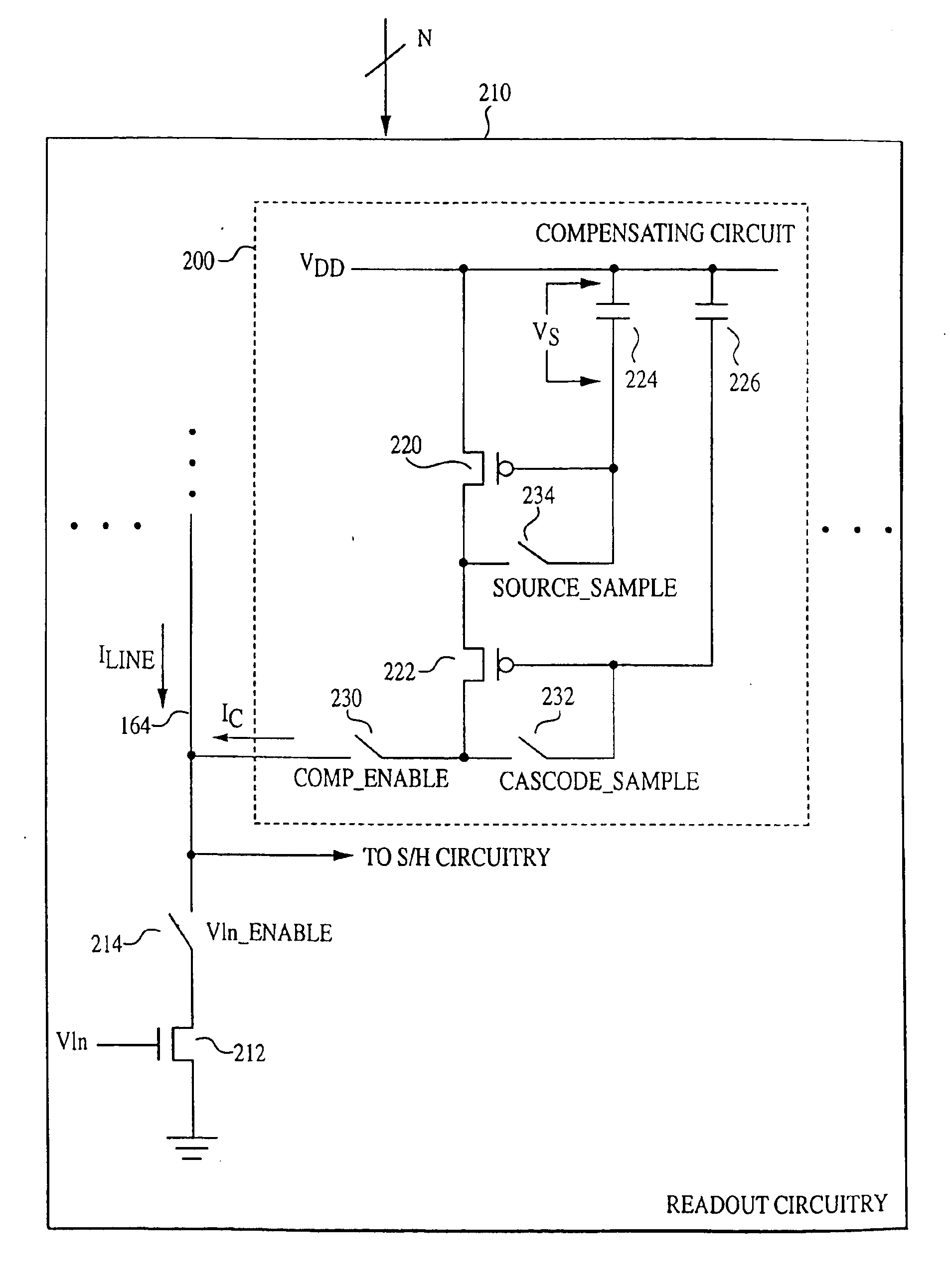
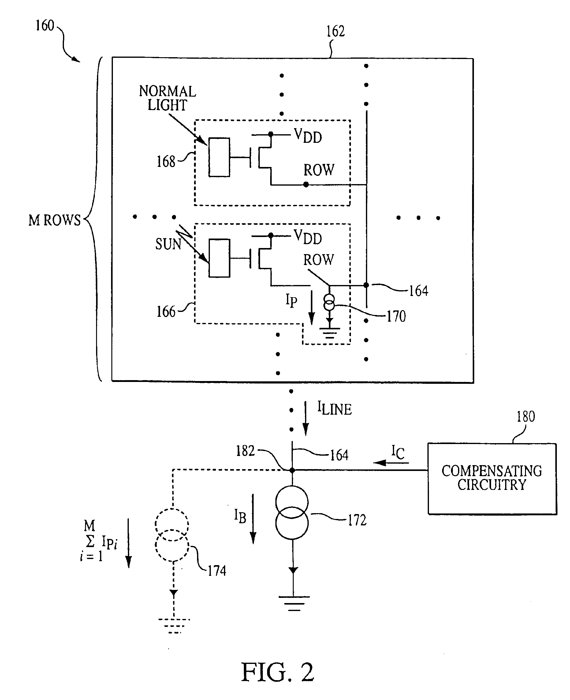
The invention provides circuits, methods, and systems in which a current is provided to compensate for spurious current while receiving signals through a line. For example, the spurious current can be sensed and the compensating current can be approximately equal to the sensed spurious current. The spurious current could include photocurrent from a bright light, and the compensating current can prevent bright light effects.

Problems solved by technology

In circuit 100 and other circuits, problems can be caused by undesired currents, such as photocurrents, that affect signals provided through lines.
Although spurious current could result from various undesired processes, it is especially problematic in a CMOS image sensor implemented in silicon.
Instead, such photoelectrons can produce an undesired photocurrent on certain other nodes in the pixel circuitry.
In addition to row / column arrays, the spurious current problem can also arise in other arrays and configurations in which light sensing pixels or other signal-providing elements provide signals through readout lines.

Method used


Image

  • Providing current to compensate for spurious current while receiving signals through a line
  • Providing current to compensate for spurious current while receiving signals through a line
  • Providing current to compensate for spurious current while receiving signals through a line

Examples


Embodiment Construction

The following detailed description refers to the accompanying drawings, which form a part hereof and which show by way of illustration specific implementations of the invention. These implementations are described in sufficient detail to enable those skilled in the art to practice the invention, and it is to be understood that other implementations may be utilized and that structural, logical, and electrical changes may be made without departing from the spirit and scope of the invention. The following detailed description is, therefore, not to be taken in a limiting sense, and the claims indicate the scope of protection sought.

FIG. 2 shows circuit 160 with array 162, illustratively a row / column image sensing array similar to array 110 in FIG. 1. The invention is also applicable, however, to other arrays and configurations in which light sensing pixels or other signal-providing elements provide signals on readout lines on which spurious current can occur.

Within array 162, light sens...


PUM


Abstract

Circuits, methods, and systems are disclosed in which a current is provided to compensate for spurious current while receiving signals through a line. For example, the spurious current can be sensed and the compensating current can be approximately equal to the sensed spurious current. The spurious current could include photocurrent from a bright light, and the compensating current can prevent bright light effects.

Description

FIELD OF THE INVENTIONThe invention relates to techniques for receiving signals from signal-providing elements through a line. Particularly, the invention relates to methods, circuits, and systems that provide current to compensate for spurious current while receiving signals through such a line.BACKGROUND OF THE INVENTIONVarious types of elements for providing signals through a line in various configurations are known. For example, U.S. Pat. No. 6,204,524 ('524), incorporated herein by reference, describes CMOS active pixel sensor (APS) arrays and compares them to other semiconductor-based imagers, including charge coupled devices (CCDs), photodiode arrays, charge injection devices, and hybrid focal plane arrays.In many known configurations, a number of light sensing elements, often called “pixels”, provide their signals through a conductive line, sometimes referred to herein as a “readout line”. In a row / column array, for example, each column typically has a readout line to receiv...

Claims


Application Information

Patent Timeline
Patent Type & Authority Patents(United States)
IPC IPC(8): H01L27/148H01L31/101H01L31/062H01L27/00H01L31/06H01L31/00H01L31/113H01L27/146H04N5/361
CPCH01L27/146H04N5/374H04N5/3658H04N5/3595H04N25/625H04N25/677H04N25/76
Inventor BARNA, SANDOR L.ROSSI, GIUSEPPE
Owner APTINA IMAGING CORP
Learn More