
Method of fabricating semiconductor device having notched gate

a technology of notched gate and semiconductor devices, which is applied in the direction of semiconductor devices, electrical equipment, transistors, etc., can solve the problems of reducing electrical conductivity, deteriorating gate oxide layer, and generally not acceptable, so as to reduce overlap capacitance, maintain gate electrode reliability, and reduce gate capacitance

Inactive Publication Date: 2005-02-22
SAMSUNG ELECTRONICS CO LTD
View PDF8 Cites 14 Cited by
  • Summary
  • Abstract
  • Description
  • Claims
  • Application Information

AI Technical Summary

Benefits of technology

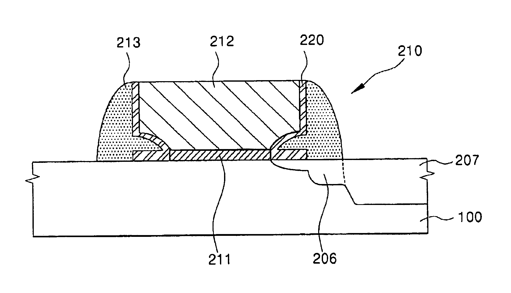
To overcome the above described problems, the present invention provides a semiconductor device capable of forming a shallow junction by a low energy ion-implanting process while maintaining reliability of the gate electrode, while reducing gate capacitance according to the reduction of gate length by forming a notched gate, and while reducing an overlap capacitance between the gate and the source / drain extension.
In another aspect, the present invention is directed to a method of fabricating a semiconductor device, comprising the steps of: sequentially providing a gate oxide layer and a gate polysilicon layer on a silicon substrate; etching a notched gate electrode in the gate polysilicon layer by applying an etching condition so as to increase a selectivity ratio in the gate oxide layer, the notched gate electrode including a notch along an outer side surface of a lower portion such that a top portion of the notched gate electrode is wider than the lower portion; providing a gate poly oxide layer on the top portion and outer side surface of the notched gate electrode and on the substrate; removing a portion of the gate poly oxide layer except for a portion of the outer side surface in the region of the notch; forming a lightly doped drain LDD region by applying a low energy first ion implanting process; forming a gate spacer adjacent the gate poly oxide layer; and forming a deeply doped region by applying a second ion implanting process to provide a deep source / drain region.

Problems solved by technology

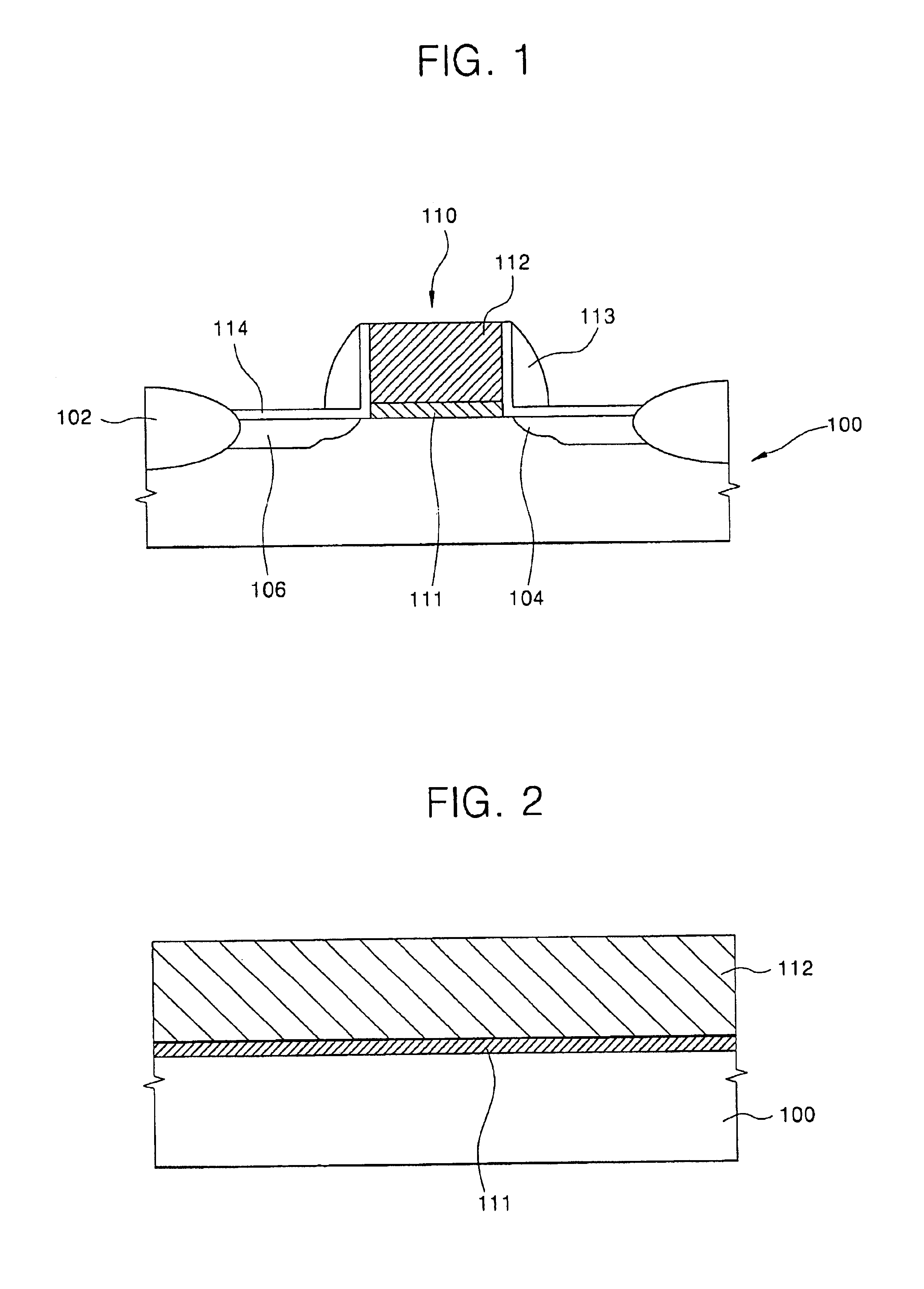
Such an LDD region can eliminate the problem of hot carriers, but this approach can also result in deterioration of the gate oxide layer 111.
Additionally, the resistance of the LDD region is higher than a comparable highly doped region because lighter dopant levels in the LDD region reduces electrical conductivity in the silicon substrate.
Therefore, it is not generally acceptable that the performance of the semiconductor device, including the LDD region, is deteriorated with the application of lower voltages.

Method used


Image

  • Method of fabricating semiconductor device having notched gate
  • Method of fabricating semiconductor device having notched gate
  • Method of fabricating semiconductor device having notched gate

Examples


Embodiment Construction

Reference is now made in detail to preferred embodiments of the present invention, an example of which is illustrated in the accompanying drawings.

Initially, an isolation layer of a field oxide and a channel ion implanting process are generally applied to a silicon substrate. The channel ion implanting process is performed to fabricate a lightly doped drain LDD region.

Referring to FIG. 2, a gate oxide layer 111 and a gate polysilicon layer 112 are fabricated on the silicon substrate 100. The gate oxide layer may be formed of a material comprising, for example, silicon oxide SiO2, silicon oxi-nitride SiOxNy, zirconium oxide ZrO2, hafnium oxide HfO2, tantalum oxide Ta2O5, or aluminum oxide Al2O3. Silicon nitride Si3N4 may alternatively be used. Silicon oxide SiO2 is preferred.

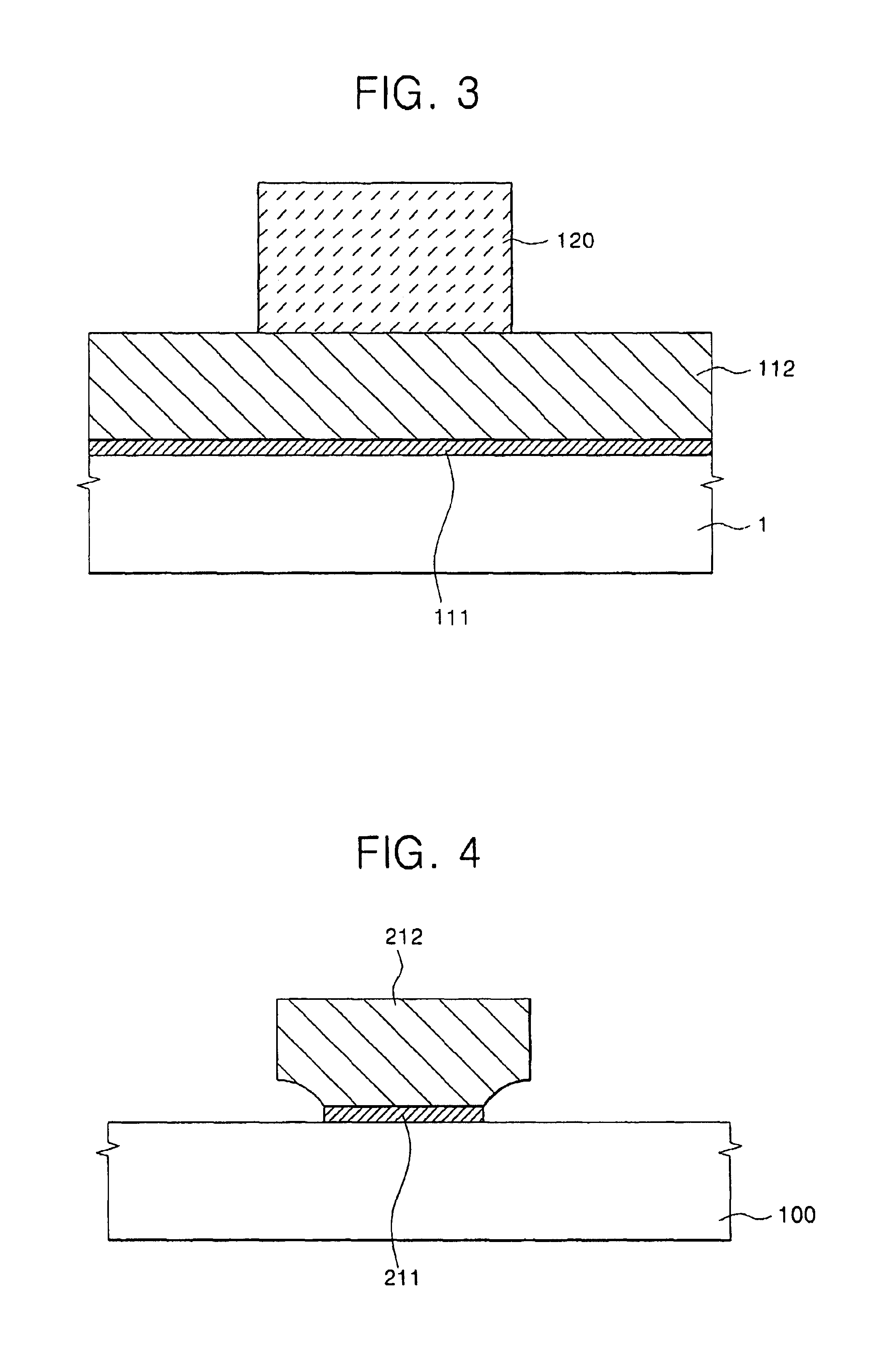
Referring to FIG. 3, a photoresist 120 is coated on the gate polysilicon layer 112, and developed to from a pattern.

Referring to FIG. 4, after patterning the photoresist 120, the gate polysilicon layer 112 is dry...


PUM


Abstract

A semiconductor device includes: a silicon substrate; a source / drain region formed in the substrate including a lightly doped region and an adjacent heavily doped region, the depth of the heavily doped region being greater than the depth of the lightly doped region; a gate oxide layer on the silicon substrate; and a notched gate electrode on the substrate, the notched gate electrode including a notch along an outer side surface of a lower portion such that a top portion of the notched gate electrode is wider than the lower portion, the gate oxide layer extending between the interface of the notched gate electrode and the substrate, and a gate poly oxide layer provided along an outer side surface of the notched gate electrode and along an inner wall of the notch, a portion of the lightly doped region being under the notch.

Description

BACKGROUND OF THE INVENTION1. Field of the InventionThe present invention relates to a method for fabricating a semiconductor device having a notched gate, and more particularly, to a method for fabricating a semiconductor device having a notched gate wherein the semiconductor device is capable of forming a shallow junction through a low-energy ion implantation process, while maintaining reliability in an oxide gate.2. Description of the Related ArtWhen a semiconductor device is fabricated on a silicon substrate, an electric field of high strength is generated in an interface, or junction, region between a doping region and a channel region doped with high-density impurity on the bottom of a gate electrode of the substrate. Such an electric field of high strength continuously causes hot carriers to flow in the direction of the gate electrode, particularly at the bottom of the gate oxide layer, exposing the thin and weak gate oxide layer of about 40 to 100 Å in thickness to possible ...

Claims


Application Information

Patent Timeline
Patent Type & Authority Patents(United States)
IPC IPC(8): H01L21/02H01L29/66H01L21/28H01L21/336H01L29/78H01L29/40H01L29/49H01L21/338
CPCH01L21/28114H01L29/7833H01L29/6659H01L29/66598H01L29/4983H01L21/28123H01L21/18
Inventor RYU, HYUK-JUKO, YOUNG-GUN
Owner SAMSUNG ELECTRONICS CO LTD
Learn More