Variable candela strobe

a candela and variable technology, applied in the field of candela strobes, can solve the problems of arcing, use of voltage doublers, and limit the range of candelas that can be reliably achieved,

Inactive Publication Date: 2005-02-15
HONEYWELL INT INC
View PDF17 Cites 11 Cited by
  • Summary
  • Abstract
  • Description
  • Claims
  • Application Information

AI Technical Summary

Problems solved by technology

However, there are limitations on the range of candela (intensity) that can be reliably achieved.
One problem is that to flash the tube requires that the voltage across it be greater than a predetermined threshold amount (e.g. 180 volts) for reli...

Method used


Image

  • Variable candela strobe
  • Variable candela strobe
  • Variable candela strobe

Examples


Embodiment Construction

While embodiments of this invention can take many different forms, specific embodiments thereof are shown in the drawings and will be described herein in detail with the understanding that the present disclosure is to be considered as an exemplification of the principles of the invention and is not intended to limit the invention to the specific embodiment illustrated.

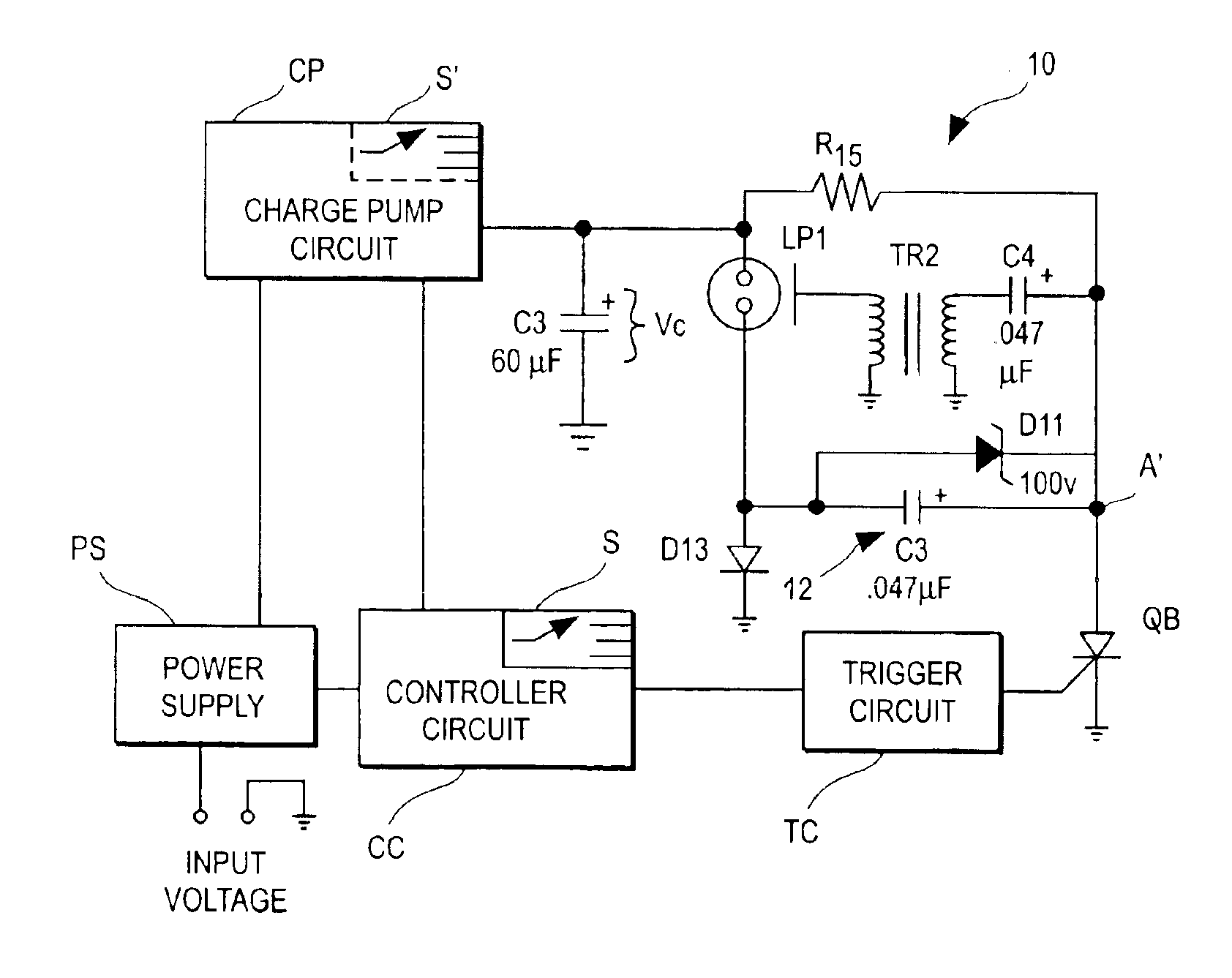
The disadvantages of the prior art above can be overcome with a power supply in accordance with the invention. A more controlled voltage is achieved across the flash tube using a voltage booster circuit that is not a “doubler” but rather an “adder” type circuit. The present circuit operates significantly differently than the prior art circuits.

FIGS. 2A, 2B illustrate two different embodiments 10, 10-1 of strobe alarms in accordance with the invention. In both FIGS. 2A, 2B the maximum voltage capable of being applied across tube LP12 is the sum of VC, the voltage across capacitor C3 plus the voltage across an off-set ci...


PUM


Abstract

A selectable candela strobe alarm unit includes an energy storage circuit to reliably discharge a gas filled output device. The circuit includes a primary energy storage capacitor and a secondary energy storage capacitor. The capacitors can be configured in series or in parallel to produce a selected candela output from the gas filled output device.

Description

FIELD OF THE INVENTIONThe invention pertains to strobe devices of a type used in alarm systems. More particularly, the invention pertains to strobe devices with selectable candela outputs.BACKGROUND OF THE INVENTIONStrobe devices require the application of a relatively high voltage across a flash tube in order to produce a gaseous discharge in the tube. In known devices, this high voltage is achieved by using a charge pump to transfer energy to an internal capacitor from an external energy source. The external source typically can be nominally 12 volts or 24 volts.The capacitor is coupled in parallel with the flash tube and provides the energy for the flash. The amount of light from the flash tube is directly proportional to the energy stored in the capacitor that is discharged into the flash tube.A single capacitor can be charged to various voltages in order to provide a multi-candela (multi-intensity) unit. However, there are limitations on the range of candela (intensity) that ca...

Claims


Application Information

Patent Timeline
IPC IPC(8): G08B5/38G08B5/22
CPCG08B5/38
Inventor TICE, LEE D.FISLER, CHARLES F.HA, SIMON
Owner HONEYWELL INT INC
Why Eureka
Try Eureka