Eureka AIR delivers breakthrough ideas for toughest innovation challenges, trusted by R&D personnel around the world.

Gradual correction of corneal refractive error using multiple inlays

Inactive Publication Date: 2005-02-15
ACUFOCUS +1
View PDF23 Cites 121 Cited by
  • Summary
  • Abstract
  • Description
  • Claims
  • Application Information

AI Technical Summary

Benefits of technology

It is another object of the present invention to provide a system and method for implantation of an intracorneal inlay that does not delay wound healing.
It is still another object of the present invention to provide a system and method for implantation of an intracorneal inlay that reduces the potential for scaring of the cornea.
It is yet another object of the present invention to provide a system and method for implantation of an intracorneal inlay that can be removed and / or replaced without damaging the cornea.
It is still yet another object of the present invention to provide a system and method for implantation of multiple intracorneal inlays that reduce the inhibition of the flow of nutrients through the inlay.

Problems solved by technology

However, there can be problems when microkeratomies are used for cutting the cornea.
First, irregular keratectomies or perforations of the eye can result.
Second, the recovery of vision can be rather prolonged.
However, by separating the layers in the bottom two-thirds of the stroma, it is difficult to access the separated area to insert the inlay and virtually impossible to change or modify the inlay without another extensive surgical procedure.
However, because only a certain amount of cornea can be ablated without the remaining cornea becoming unstable or experiencing outbulging (eklasisa), this technique may not be especially effective in correcting very high myopia.
Use of these instruments may result in damage or imprecision in the cut or formation of the desired area in which the implant is placed.
Gluing the lens to the cornea, not only can result in some loss of the lens transparency to the media, but it also results in a lens that, if removed, would likely result in scaring of the cornea.
Further scaring can result from the peripheral groove formed in the surface of the cornea.
Additionally, in the Thompson et al. procedure, the removed epithelial cells are discarded, which can significantly delay wound healing.
This can potentially increase the thickness of the required lens, and thus inhibit the flow of nutrients through the lens.

Method used


Image

  • Gradual correction of corneal refractive error using multiple inlays
  • Gradual correction of corneal refractive error using multiple inlays
  • Gradual correction of corneal refractive error using multiple inlays

Examples


Embodiment Construction

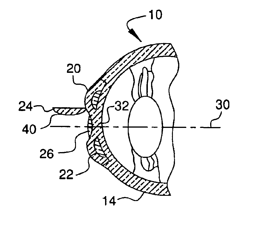
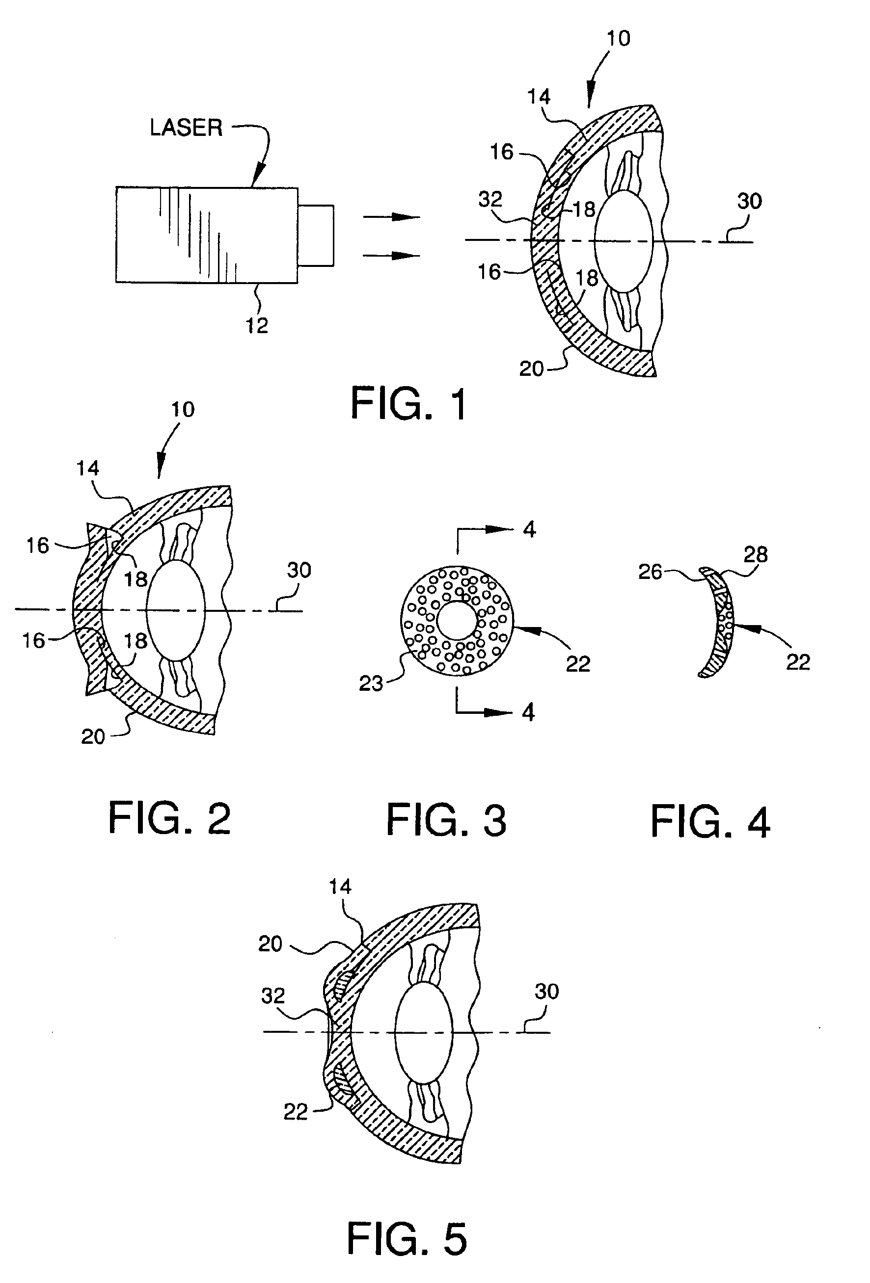
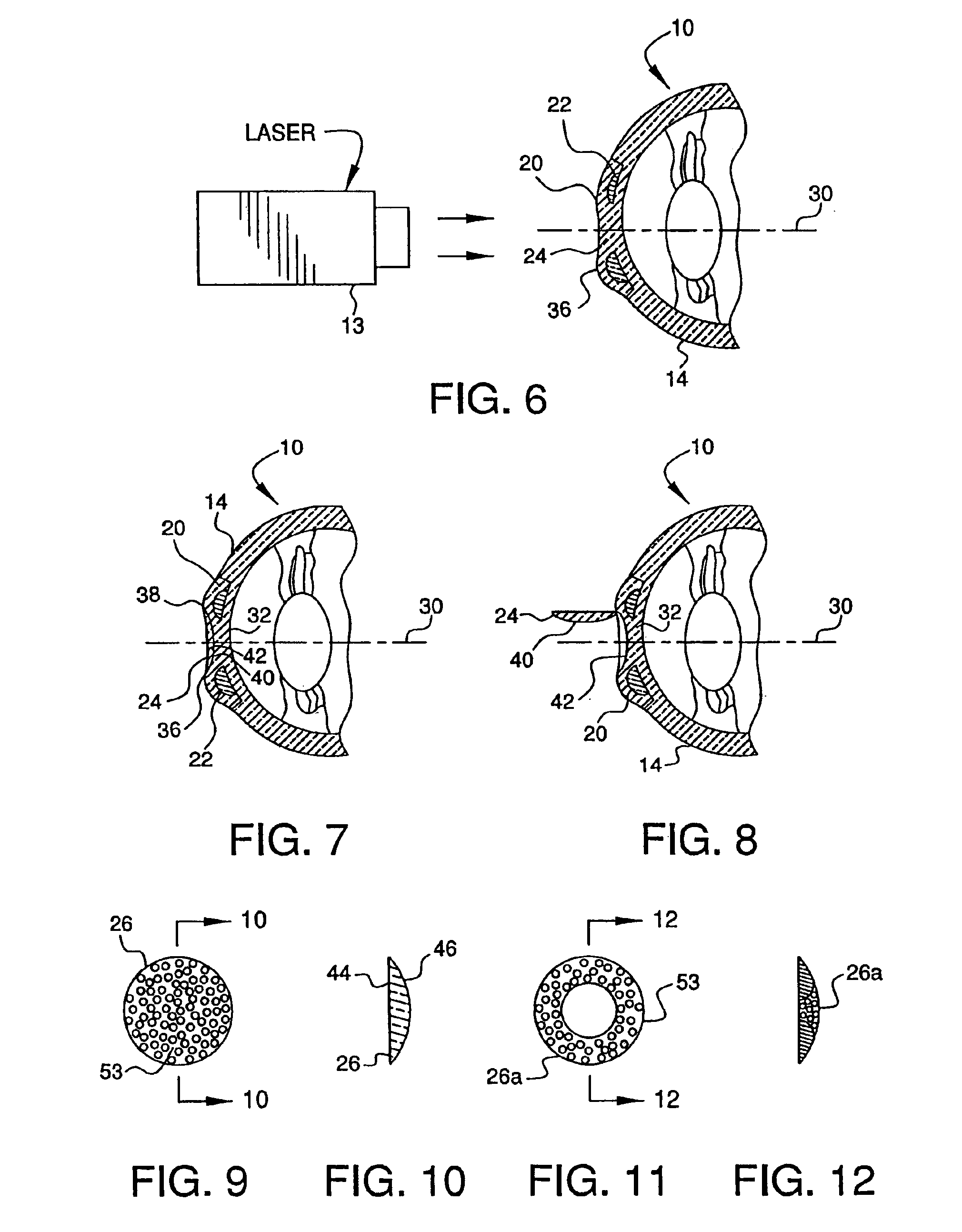
As initially shown in FIGS. 1-17, the refractive properties of eye 10 can be altered using laser 12 to separate an inner portion of the cornea 14 into first internal corneal surface 16 and second internal corneal surface 18. This separation creates an internal corneal flap 20 in the cornea 14, under which a first component or intracorneal inlay 22 can be placed. Additionally, as discussed in more detail below, a second flap 24 can be formed in the surface of the cornea, and a second separate component or intracorneal inlay 26 can be inserted under the second flap (see FIGS. 7-17). Each inlay itself changes the shape of the cornea and thus the refractive properties thereof, and thus by inserting either or both inlays, it is possible to correct myopia, hyperopia and / or astigmatism.

To begin, the refractive error in the eye is measured using wavefront technology, as is known to one of ordinary skill in the art. The refractive error measurements are transmitted to a computerized lathe (n...


PUM


Abstract

A system adapted to modify refractivity of a cornea of an eye, including a first component, and adapted to be implanted at a first depth in the cornea. A second component, separate from the first component, is adapted to be implanted at a second depth in the cornea at a position relative to the first component, such that an axis passing through the eye parallel to the optical axis passes through the second component without passing through the first component. The second depth is closer to the front surface of the cornea than is the first depth.

Description

FIELD OF THE INVENTIONThe present invention relates to a method and apparatus for changing the refractive properties of the cornea by implanting multiple inlays in the cornea. More particularly, the present invention relates to a system and method for changing the refractive properties of the cornea by implanting two inlays at different depths in the cornea and at different lateral positions with respect to the optical axes.BACKGROUND OF THE INVENTIONA conventional method for correcting the refractive error in a cornea is keratophakia, i.e., implantation of a lens inside the cornea. Keratophakia uses an implant, which is placed into the cornea approximately equidistant from the exterior surface of the cornea and the interior surface. The procedure is usually done by first preparing a lens from corneal donor tissue or synthetic material using a cryo-lathe. The lens is implanted by removing a portion of the cornea with a device called a microkeratome, and the tissue is sutured back in...

Claims


Application Information

Patent Timeline
IPC IPC(8): A61F2/14A61B18/20A61F9/007A61N5/06
CPCA61F2/147Y10S623/906
Inventor PEYMAN, GHOLAM A.
Owner ACUFOCUS
Why Eureka
Eureka Blog
Learn More