Eureka AIR delivers breakthrough ideas for toughest innovation challenges, trusted by R&D personnel around the world.

Electrosurgical systems and methods for recanalization of occluded body lumens

a technology of electrosurgical and occluded body, applied in the field of electrosurgical systems, can solve the problems of affecting the operation, affecting the operation, and affecting the effect of the procedure, so as to minimize the current flow through the stent, and eliminate the potential for contact

Inactive Publication Date: 2005-02-15
ARTHROCARE
View PDF359 Cites 359 Cited by
  • Summary
  • Abstract
  • Description
  • Claims
  • Application Information

AI Technical Summary

Benefits of technology

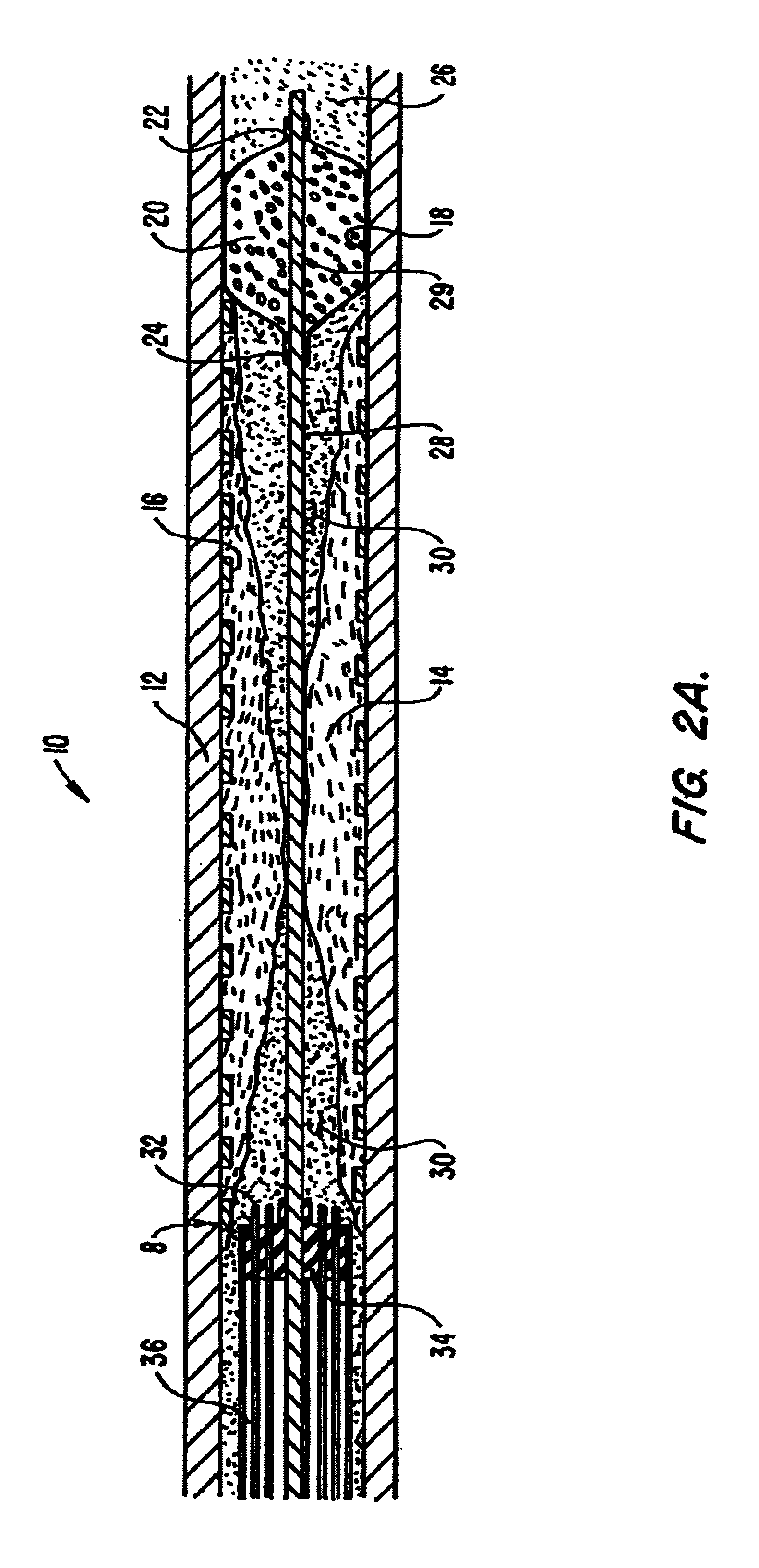
According to one embodiment of the present invention, the active and return electrode(s) are configured such that the charge on the electrodes, and the intensity of the electric field, is sufficient to ablate or volumetrically remove the occlusive media in contact with, or in close proximity to, the active electrode(s). Since, in this embodiment, current is not flowing into the occlusive media, the modification or ablation of the occlusive material is accomplished at substantially lower temperatures than traditional electrosurgery, which reduces collateral tissue damage. In addition, the current does not penetrate beyond the target site, which further reduces damage to the surrounding lumenal wall. Moreover, the electric current is precisely controlled, which allows the device to be used adjacent to electrically sensitive structures, such as nerves, the heart or the spine. Another advantage of the present invention is that the alternating current flow between the electrodes is more uniform across the surface of the return electrode, rather than collecting at the distal corner of the return electrode, as may occur with traditional electrosurgical devices.
is that the alternating current flow between the electrodes is more uniform across the surface of the return electrode, rather than collecting at the distal corner of the return electrode, as may occur with traditional electrosurgical devices.
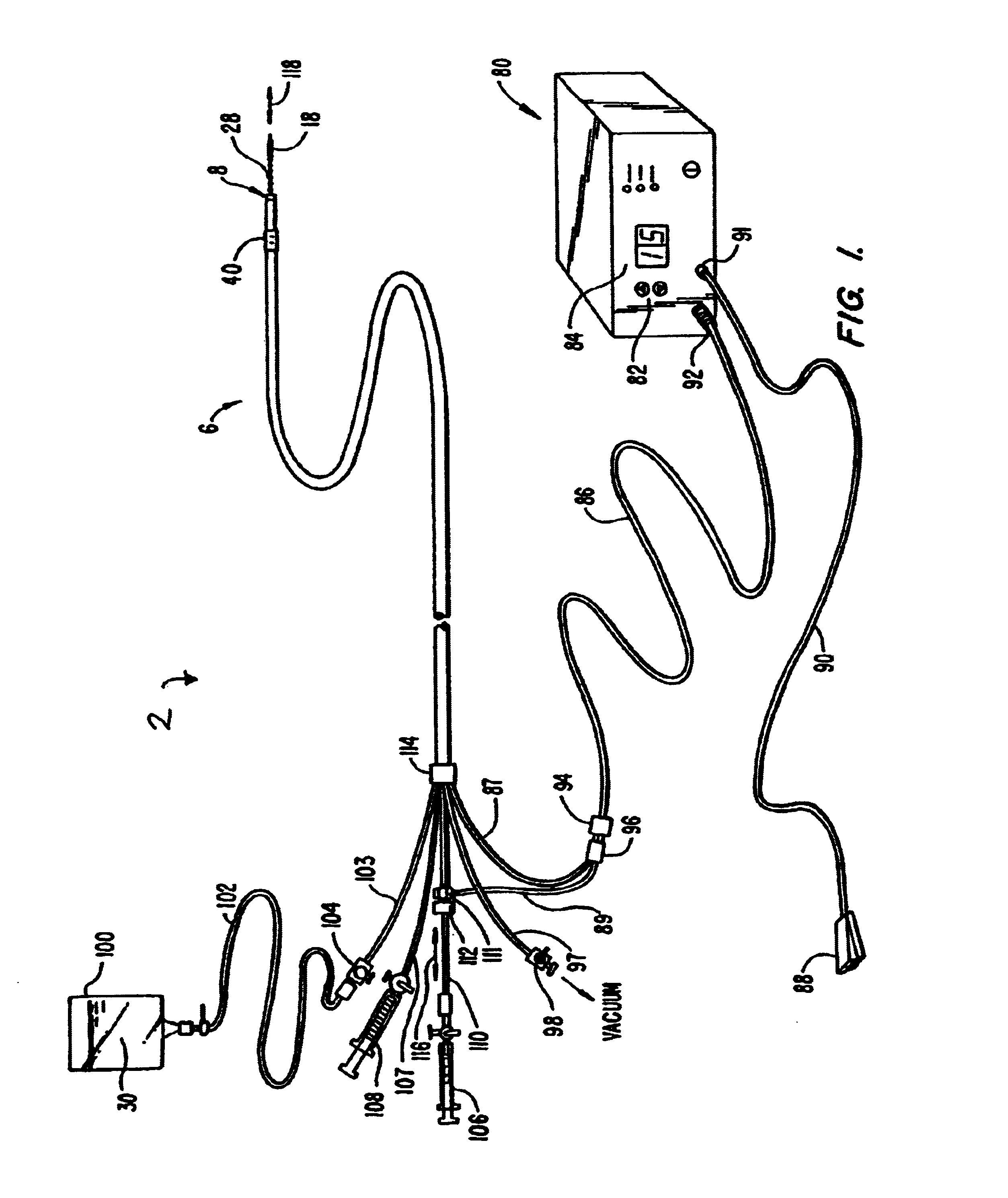
In another application, an electrosurgical catheter is advanced within the body passage such that an active electrode and a return electrode are positioned near the occlusive media. A high frequency voltage is applied between the active and return electrodes as described above, to produce a charge sufficient to volumetrically remove the occlusive media in situ. In exemplary embodiments, the high frequency voltage is sufficient to effect molecular dissociation or disintegration of the occlusive media, thus converting the solid media into non-condensable gases or other low molecular weight ablation by-products. According to the present invention, the return electrode is insulated from the active electrode and the patient's body to eliminate the potential for contact between the return electrode and the body lumen, which could otherwise cause thermal damage to the walls of the vessel.
The present invention is particularly useful in a lumen containing a lumenal prosthesis, such as a stent, stent-graft or graft, which may be metallic, non-metallic or a non-metallic coated metallic structure. Restenosis often occurs when artheromatous material or thrombus move or from in or around the cylindrical wall of the prosthesis to partially occlude the body passage. In this application, it is particularly useful to insulate the return electrode from the conductive stent, and to control the flow of current at the target site to minimize current flow through the stent.
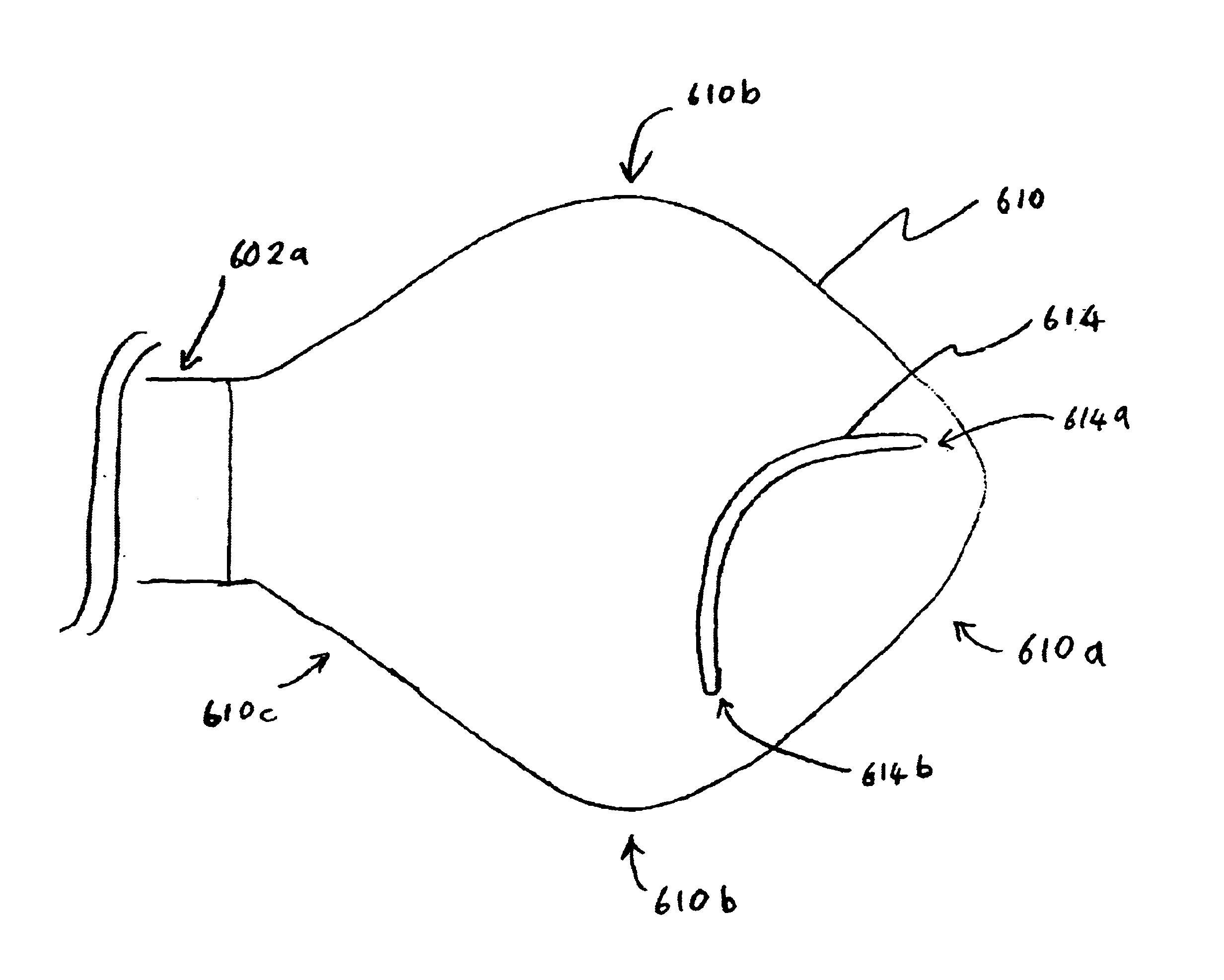
In one aspect of the invention, there is provided a catheter having a spacer or electrode support and a plurality of active electrodes on the electrode support; wherein the electrode support includes a support distal portion, and the support distal portion tapers from narrow to broad in a proximal direction to a position of maximum width or girth of the electrode support. In one embodiment, the plurality of active electrodes are located on the support distal portion at a location distal to the position of maximum width of the electrode support, and the position of maximum width of the electrode support is wider than the width or diameter of the catheter shaft.
In another aspect of the invention, there is provided a catheter including a plurality of active electrode leads or connection wires, wherein each of the plurality of active electrode leads is a hybrid electrode lead including a distal portion comprising a first metallic composition, and a proximal portion comprising a second metallic composition. In one embodiment, the first metallic composition comprises platinum or platinum / iridium, and the second metallic composition comprises molybdenum. In one embodiment, an exposed distal portion of each active electrode lead forms an active electrode terminal, including a first free end, a loop portion, and a second connected end, wherein the first free end terminates in the electrode support, the loop portion defines a gap between the active electrode and the electrode support, and the second connected end is in communication with the active electrode lead.

Problems solved by technology

As a result of these occlusions, the organ or extremity to which blood is to be supplied is compromised and the patient may experience a myocardial infarction or stroke.
However, this successful procedure is overshadowed by the occurrence of restenosis, a re-narrowing of the artery.
Although this method is successful in preventing recoil of the vessel wall, restenosis will often still occur.
Unfortunately, the Spears device does not adequately prevent the spontaneous elastic recoil of the arterial wall.
Thus stenting in and of itself is ineffective in preventing restenosis due to the occurrence of cellular proliferation.
Likewise, balloon dilation in combination with localized heating does not adequately prevent restenosis since the vessel wall tends to spontaneously return to its original occluded shape.
One major disadvantage of these procedures is that it is difficult to selectively apply the energy to the invasive tissue without causing thermal damage to the body lumen wall.
In particular, methods that apply energy, such as RF energy, directly to the stent will often cause thermal damage to the surrounding body lumen in which the stent is anchored.

Method used


Image

  • Electrosurgical systems and methods for recanalization of occluded body lumens
  • Electrosurgical systems and methods for recanalization of occluded body lumens
  • Electrosurgical systems and methods for recanalization of occluded body lumens

Examples


first embodiment

tissue ablation region 8 of catheter 6 is shown in FIGS. 3A and 3B. As shown, two active electrodes 50a and 50b are secured within an electrically insulating support member 34. The electrodes 50a, 50b are preferably composed of a refractory, electrically conductive metal or alloy, such as platinum, titanium, tantalum, tungsten, stainless steel, gold-plated, copper, nickel, and the like. The support member 34 is secured to the distal end of catheter 6 with a biocompatible adhesive 60 between support member 34 and outer sleeve 36. An electrically insulating sleeve 54 preferably extends above the distal plane of active electrodes 50a, 50b by a distance Hs. A central lumen in support member 34 provides a passageway for guide wire 28 that permits axial displacement and rotation of tissue ablating region 8 relative to guide wire 28.

In an exemplary embodiment, the support member 34 will comprise an inorganic insulator, such as ceramic, glass, glass / ceramic or a high resistivity material, s...

third embodiment

tissue ablation region 8 is illustrated in FIGS. 6A and 6B. Many of the elements of this embodiment are the same as those of previously described embodiments, and therefore their description will not be repeated. As shown, a single active electrode 200 is secured within support member 34. Active electrode 200 preferably has an L-shaped distal end so that a distal portion 202 of electrode 200 extends radially outward along the distal surface of support member 34. As before, catheter 6 / electrode 200 is rotated in both directions, as the region 8 is advanced through the lumen to recanalize the lumen.

fourth embodiment

tissue ablation region 8 is illustrated in FIGS. 7A and 7B . Many of the elements of this embodiment are the same as in previous embodiments, and therefore will not be repeated. As shown, six active electrodes 66a-66f are secured within inorganic support member 34. An annular irrigation lumen 56 and an aspiration lumen 58 are provided to inject electrically conductive fluid 30 and remove gaseous products of ablation 48 from the site of recanalization. When high frequency voltage is applied between the return electrode 28 and active electrodes 66a-f, a vapor layer 64 forms at and around active electrodes 66a-f with concomitant volumetric removal (ablation) of the occlusive media 14. For this embodiment and that shown in FIGS. 8A and 8B, rotation of catheter 6 may be limited to + / −30 degrees due to the greater number and circumferential distribution of active electrodes. The power or current supplied to each electrode 66a-f may be individually controlled by active or passive mechanism...


PUM


Abstract

The present invention comprises electrosurgical apparatus and methods for maintaining patency in body passages subject to occlusion by invasive tissue growth. The apparatus includes an electrode support disposed at a shaft distal end having at least one active electrode arranged thereon, and at least one return electrode proximal to the at least one active electrode. In one embodiment, a plurality of active electrodes each comprising a curved wire loop portion are sealed within a distal portion of the electrode support. The apparatus and methods of the present invention may be used to open and maintain patency in virtually any hollow body passage which may be subject to occlusion by invasive cellular growth or invasive solid tumor growth. Suitable hollow body passages include ducts, orifices, lumens, and the like, with exemplary body passages including the coronary arteries. The present invention is particularly useful for reducing or eliminating the effects of restenosis in coronary arteries by selectively removing tissue in-growth in or around stents anchored therein.

Description

BACKGROUND OF THE INVENTIONThe present invention relates generally to apparatus and methods for maintaining patency in body passages and more particularly to a catheter system capable of selectively ablating occlusive media within a body lumen. The present invention is particularly useful for the electrosurgical removal or ablation of invasive tissue growth or atheromatous material in or around an intraluminal prosthesis or stent anchored in the body lumen, whereby restenosis of the body lumen is reduced or eliminated.When a patient is suffering from atherosclerosis, significant occlusions or blockages are formed on the interior wall of the artery. As a result of these occlusions, the organ or extremity to which blood is to be supplied is compromised and the patient may experience a myocardial infarction or stroke. In less severe cases, it is often sufficient to treat the symptoms with pharmaceuticals and lifestyle modification to lessen the underlying causes of the disease. In more...

Claims


Application Information

Patent Timeline
Patent Type & Authority Patents(United States)
IPC IPC(8): A61B18/12A61B18/14A61B18/00
CPCA61B18/1206A61B18/1492A61B2218/008A61B18/1485A61B2017/003A61B2017/22038A61B2018/00214A61B2018/0041A61B2018/00422A61B2018/00577A61B2018/00583A61B2018/00702A61B2018/00827A61B2018/1213A61B2018/1253A61B2018/1273A61B2018/1467A61B2018/1472A61B2018/162A61B2218/002A61B2218/007A61B18/1233
Inventor DAVISON, PAUL O.WOLOSZKO, JEAN
Owner ARTHROCARE
Why Eureka
Eureka Blog
Learn More