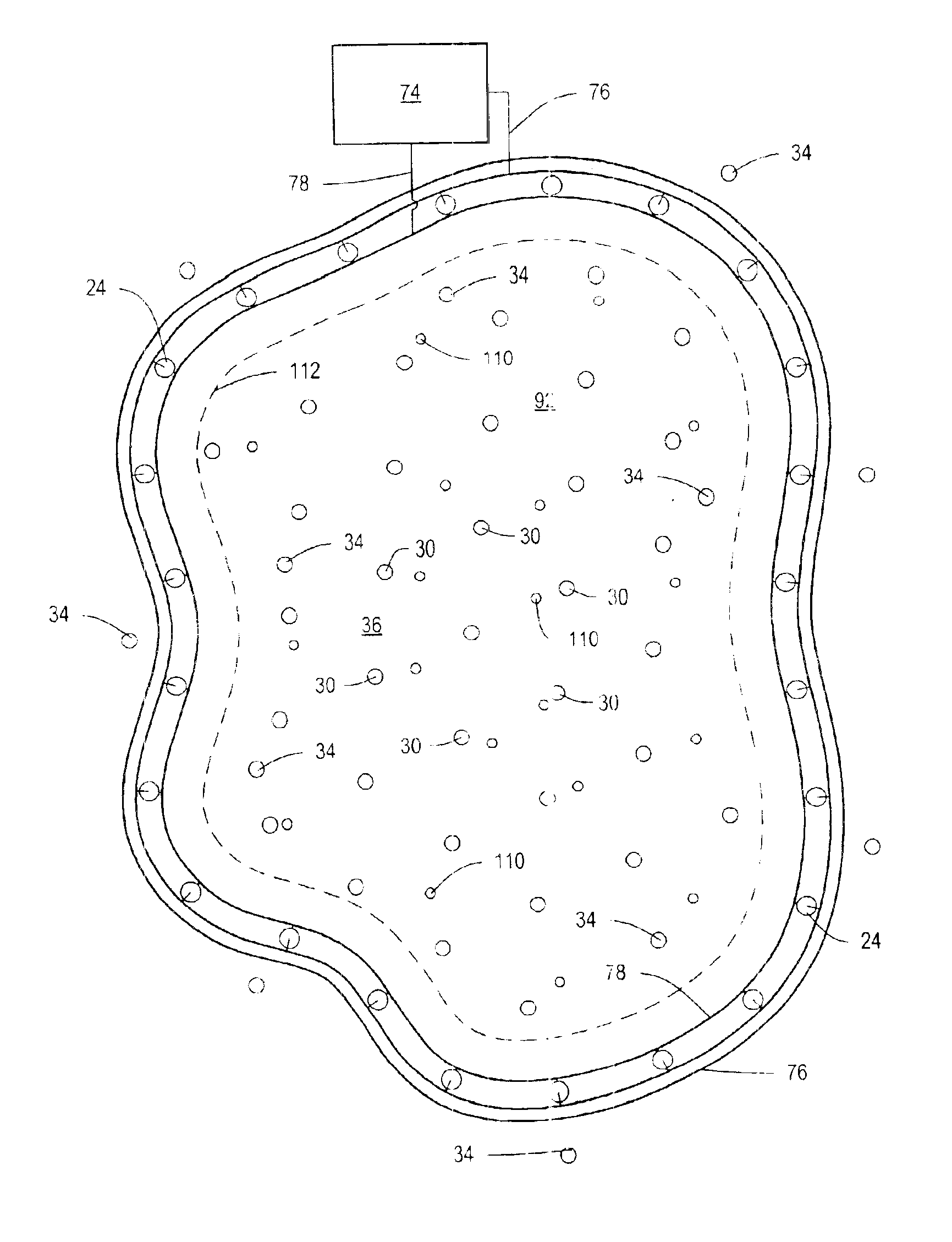
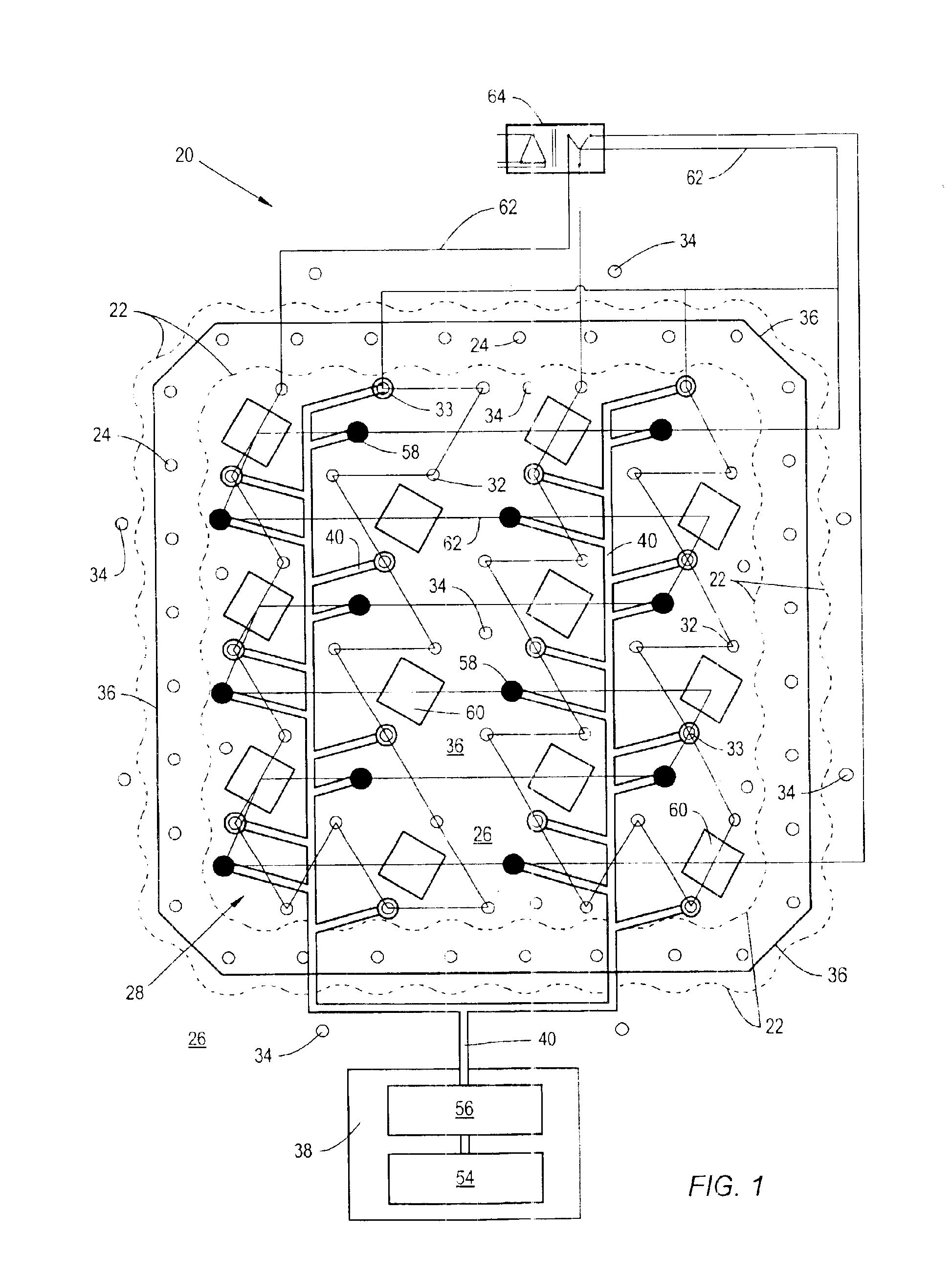
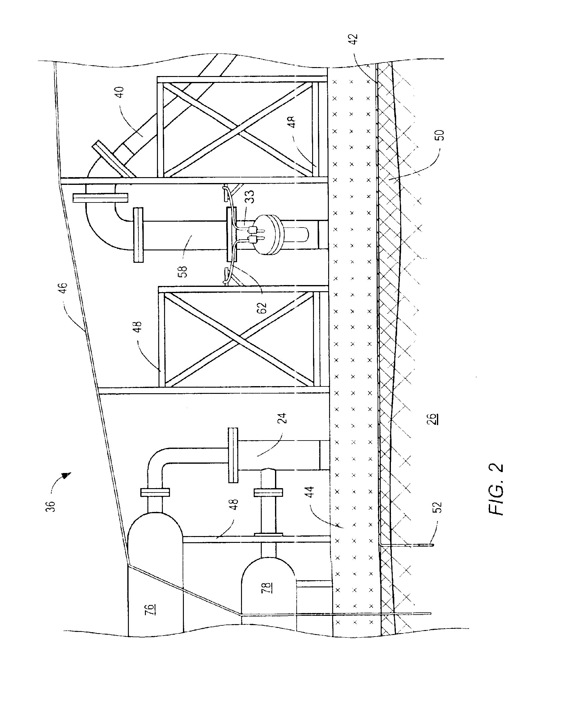
Freeze wells may be used to create a barrier at a perimeter of a treatment area of contaminated soil. “Freeze wells” refers to wells or openings in the ground that are used to cool a portion of the formation to temperatures sufficient to freeze water within the ground. “Treatment area” refers to a volume of soil that is to be processed by an in situ soil remediation method. The freeze wells may form a frozen barrier along the perimeter. The barrier may be impermeable. The barrier may inhibit fluid flow into or out of the treatment area. Inhibiting fluid flow out of the treatment area may prevent the spread of
contamination from the contaminated soil to uncontaminated soil. Inhibiting fluid flow into the treatment area may reduce the amount of fluid removed from the treatment area. A reduced amount of fluid removed from a treatment area may reduce the size, cost and operational expense of equipment that treats fluid removed from the ground. Inhibiting fluid flow into the treatment area may limit
water flow into the treatment area. For an in situ
thermal desorption (ISTD) remediation system, inhibiting
water flow into a treatment area may make remediating the soil economically viable.
Suction pumps and / or injectors may be used during formation and / or after formation of a frozen barrier. In a treatment area through which water flows, suction pumps and or injectors may be operated to reduce water flow so that a frozen barrier forms. In an embodiment, suction wells are installed on an inward side and an outward side of where a frozen barrier is to be formed. The suction wells are operated to minimize a pressure differential between the inward suction wells and the outward suction wells so that fluid flow between inward suction wells and outward suction wells is minimized. The freeze wells are activated to form an interconnected low temperature zone that is below a temperature needed to form a frozen barrier. After formation of the low temperature zone, the power supplied to the suction wells may be reduced to allow water or other fluid to enter into the low temperature region between the suction wells. The water or other fluid may freeze within the low temperature zone.
In some soil remediation system embodiments, suction pumps may be used to remove water from the soil before or simultaneously with activation of heater wells within the treatment area. The suction pumps remove water to reduce the amount of water that the heater wells need to vaporize during soil remediation. Water removed from the soil may be treated in a treatment facility to remove or reduce
contamination in the water.
Refrigerant in freeze wells may reduce
soil temperature between freeze wells low enough to form of a frozen barrier between the freeze wells. Water presence in a low temperature zone may allow for the formation of a frozen barrier. The frozen barrier may be a monolithic, impermeable structure. After the frozen barrier is established, the energy requirements needed to maintain the frozen barrier may be significantly reduced, as compared to the energy costs needed to establish the frozen barrier. In some embodiments, the reduction in cost may be a factor of 10 or more. In other embodiments, the reduction in cost may be less dramatic, such as a reduction by a factor of about 3 or 4.
A drive fluid may be used in conjunction with a soil remediation system that utilizes freeze wells. The drive fluid may be used to move contaminants within the soil toward extraction wells. In certain embodiments, some extraction wells may be converted to injection wells to allow a drive fluid to be injected into the soil by detaching the wells from the vacuum system and attaching the wells to an injection system. A ring of extraction wells may be converted to injection wells. After the drive fluid is injected into the soil through the wells, the injection wells may be converted back to extraction wells by reattaching the wells to the vacuum system. A drive fluid may be utilized near an end of a soil remediation process to sweep residual contamination toward extraction wells so that the contamination may be removed from the soil. Increased permeability within the soil due to heating the soil may facilitate removal of residual contamination using a drive fluid. In some embodiments, some soil remediation wells may be injection wells coupled to an injection system so that no extraction wells need to be converted to injection wells during remediation.
After contamination within a treatment area is removed or reduced to acceptable levels, a soil remediation system and initial freeze wells may be deactivated. If a new barrier is to be formed around a second treatment area, heat may be transferred between the soil in which a new barrier is to be formed and the initial freeze wells using a circulated
heat transfer fluid. Using deactivated freeze wells to cool soil in which a frozen barrier is to be formed may allow for
recovery of some of the energy expended to form and maintain the initial barrier. Using the initial barrier to cool soil in which a new frozen barrier is to be formed may significantly decrease a cost of forming the new barrier. A frozen barrier that is to be thawed, a maintained frozen barrier, and / or a portion of an output
stream from a
refrigeration unit may be utilized to provide cooling for a condensate trap and / or fluid
separation system. In some soil remediation embodiments, a frozen barrier may be allowed to naturally reach
thermal equilibrium with surrounding soil. Freeze wells may be removed from the ground after soil remediation. The freeze wells or parts of the freeze wells may be reused at other locations.


