
Flat coil component, characteristic adjusting method of flat coil component, ID tag, and characteristic adjusting method of ID tag

a flat coil and component technology, applied in the field of flat coil components, can solve the problems of large fluctuations, prone to decline of thickness (d) and significant fluctuations in resonance frequency of individual products

Inactive Publication Date: 2005-02-08
LINTEC CORP
View PDF10 Cites 28 Cited by
  • Summary
  • Abstract
  • Description
  • Claims
  • Application Information

AI Technical Summary

Benefits of technology

The patent text describes a flat coil component and an ID tag that use a conductive material provided on an insulating substrate in a spiral pattern. The component includes a jumper with insulation that can be adjusted in number to change the characteristics of the component. The jumper can be made conductive or non-conductive, and can have missing electrical releasing portions or be incorporated into the number of pieces in arrangement. The technical effect of this invention is to provide a flexible and adjustable flat coil component and ID tag that can be used in various applications.

Problems solved by technology

In the conventional non-contact type ID tag, however, fluctuations of resonance frequency are significant in individual products.
However, when the insulating layer 12B is formed by coating, the precision of the thickness (that is, D) is prone to decline (fluctuations are large).

Method used


Image

  • Flat coil component, characteristic adjusting method of flat coil component, ID tag, and characteristic adjusting method of ID tag
  • Flat coil component, characteristic adjusting method of flat coil component, ID tag, and characteristic adjusting method of ID tag
  • Flat coil component, characteristic adjusting method of flat coil component, ID tag, and characteristic adjusting method of ID tag

Examples


first embodiment

(A) A First Embodiment

Referring now to the drawings, a first embodiment of a flat coil component, a characteristic adjusting method of flat coil component, ID tag, and characteristic adjusting method of ID tag according to the invention will be explained below.

(A-1) Configuration of the First Embodiment

FIG. 1 is an explanatory diagram of non-contact type ID tag using a flat coil component of the first embodiment, showing a schematic plan of a state in which the surface side of the ID tag is not covered, that is, the internal electric wiring pattern is formed and exposed directly.

In FIG. 1, an ID tag 20 of the first embodiment also comprises a flat coil 21, jumpers 22-1 to 22-7, an IC chip 23, and an IC connection wire 24.

The flat coil 21, IC chip 23, and IC connection wire 24 function same as in the prior art.

In the case of the first embodiment, a plurality of (seven pieces in FIG. 1) jumpers 22-1 to 22-7 are provided, and these jumpers 22-1 to 22-7 are arranged parallel between the...

second embodiment

(B) A Second Embodiment

Referring now to the drawings, a second embodiment of flat coil component, characteristic adjusting method of flat coil component, ID tag, and characteristic adjusting method of ID tag according to the invention will be explained below.

(B-1) Configuration of the Second Embodiment

FIG. 6 is a schematic plan (image diagram) of essential parts of the second embodiment, and same parts corresponding to the first embodiment are identified with same reference numerals.

In the ID tag 20A of the second embodiment, the flat coil 21, IC chip 23, and IC connection wire 24 are same as the ones in the first embodiment.

The ID tag 20A of the second embodiment has jumpers 22A-1 to 22A-7 as shown in FIG. 6 before the characteristic adjustment process. The first to fifth jumpers 22A-1 to 22A-5 are same as the ones in the first embodiment.

The sixth and seventh jumpers 22A-6 and 22A-7 have notches 22-6X and 22-7X formed in part of the conductive layer (see 22A in FIG. 2). These notc...


PUM

PropertyMeasurementUnit
thicknessaaaaaaaaaa
widthaaaaaaaaaa
thicknessaaaaaaaaaa

Abstract

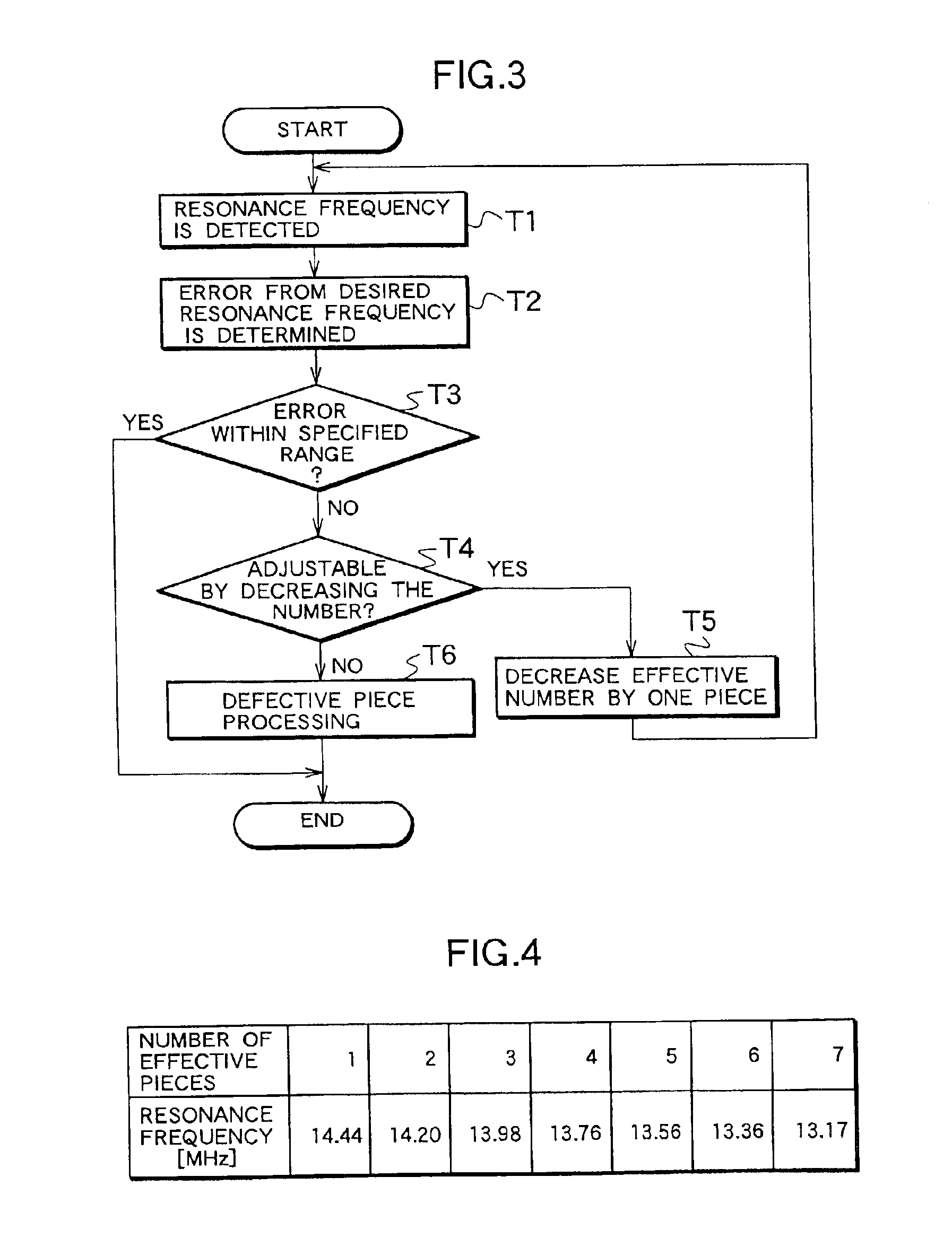
To present the ID tag including flat coil component, and characteristic adjusting method of ID tag capable of suppressing product fluctuations about the desired characteristic. The flat coil component of the ID tag of the invention comprises a flat coil composed of a conductive material provided continuously and spirally on an insulating substrate, and a jumper disposed on the flat coil with insulation, from one of inner end or outer end of this flat coil to the outside or inside of the flat coil where other end is positioned, in which the jumper is composed of a plurality of jumpers variable in the number of pieces in arrangement. The characteristic is adjusted by varying the number of effective pieces for forming the parallel arrangement.

Description

BACKGROUND OF THE INVENTION1. Field of the InventionThe present invention relates to a flat coil component, a characteristic adjusting method of the flat coil component, an ID tag, and an characteristic adjusting method of the ID tag.2. Description of the Related ArtRecently, in various processings such as individual verification, merchandise management, and distribution process, ID tags (also known as IC cards) have come to be used. In particular, non-contact type ID tags are used widely.Non-contact type ID tags are operated either by internal batteries, or by energy of radio wave or magnetic flux from a reading device of ID tags, and in the latter case, for example, necessary energy is obtained by utilizing the function of a flat coil component or an LC resonance circuit, using a flat coil component as an antenna element (Japanese Patent Laid-open No. 11-259615, Japanese Patent Publication No. 2814477).FIG. 8 explains an example of antenna pattern in a conventional non-contact typ...

Claims


Application Information

Patent Timeline
Patent Type & Authority Patents(United States)
IPC IPC(8): H01F5/00H01F21/12G06K19/077H01F41/04B42D15/10G06K19/07H01F17/00H01Q7/00
CPCG06K19/0726G06K19/07749H01F21/12H01F5/003Y10T29/4902H01F41/045G06K19/07
Inventor NIKAWA, YOSHIOMATSUSHITA, TAIGANAKATA, YASUKAZUIWAKATA, YUICHI
Owner LINTEC CORP
Learn More