
Vibratory level sensor

Inactive Publication Date: 2005-02-08
VEGA GRIESHABER GMBH & CO
View PDF19 Cites 16 Cited by
  • Summary
  • Abstract
  • Description
  • Claims
  • Application Information

AI Technical Summary

Benefits of technology

The present invention is based on the objective of disclosing a method that makes it possible to reliably and inexpensively detect level limits by means of an oscillating sensor that protrudes into the container.
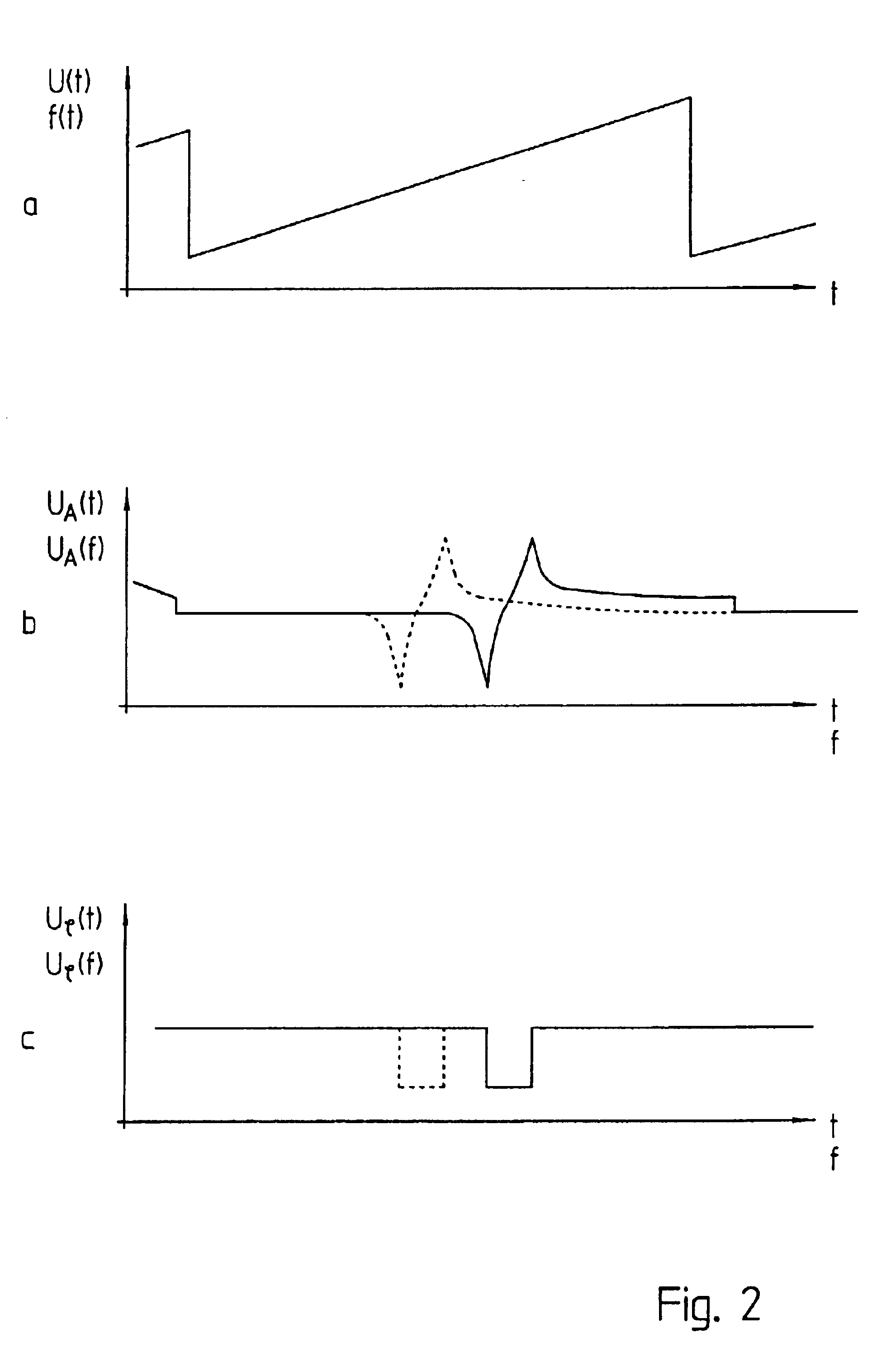
In a third preferred embodiment, a noise voltage of usually limited bandwidth or so-called pink noise is applied at the input side of an oscillating system that is preferably realized in the form of a quadrupole network. In this case, an electronic signal that now only contains certain frequency components is measured at the output as the reaction to the excitation. Most frequency portions of the broadband excitation signal are filtered out by the electromechanical oscillating system. The output signal is preferably evaluated with respect to the frequency range, for example, by means of filter banks. It would be even easier to carry out a Fourier transform of the signal from the time domain into the frequency domain. However, this would make it necessary to digitize the continuous voltage signal and to carry out a fast Fourier transform (FFT). The output amplitudes that are plotted as a function of frequency make it possible to obtain information regarding the instantaneous transmission characteristics of the vibratory system and consequently regarding whether or not the vibratory element of the sensor is covered with material.

Problems solved by technology

A problem with all these vibratory level sensors is that the oscillator must be designed such that a reliable stimulation of the oscillations and a continuous vibration of the oscillator are ensured under all operating conditions.
In order to ensure reliable vibration of the oscillator under all occurring operating conditions of the electromechanical vibratory element, complicated and expensive circuit arrangements and / or constructive measures are frequently required.
If this makes it possible to fulfill the vibratory requirements of the oscillator for different frequencies, the system oscillates rather randomly at one or the other frequency and thus makes it impossible to determine the filling state of the container.
This means that expensive measures are also required here in order to ensure that the system always oscillates at the defined, desired frequency and reliable information concerning whether a certain level has been exceeded or not reached can be obtained.

Method used


Image

  • Vibratory level sensor
  • Vibratory level sensor
  • Vibratory level sensor

Examples


Embodiment Construction

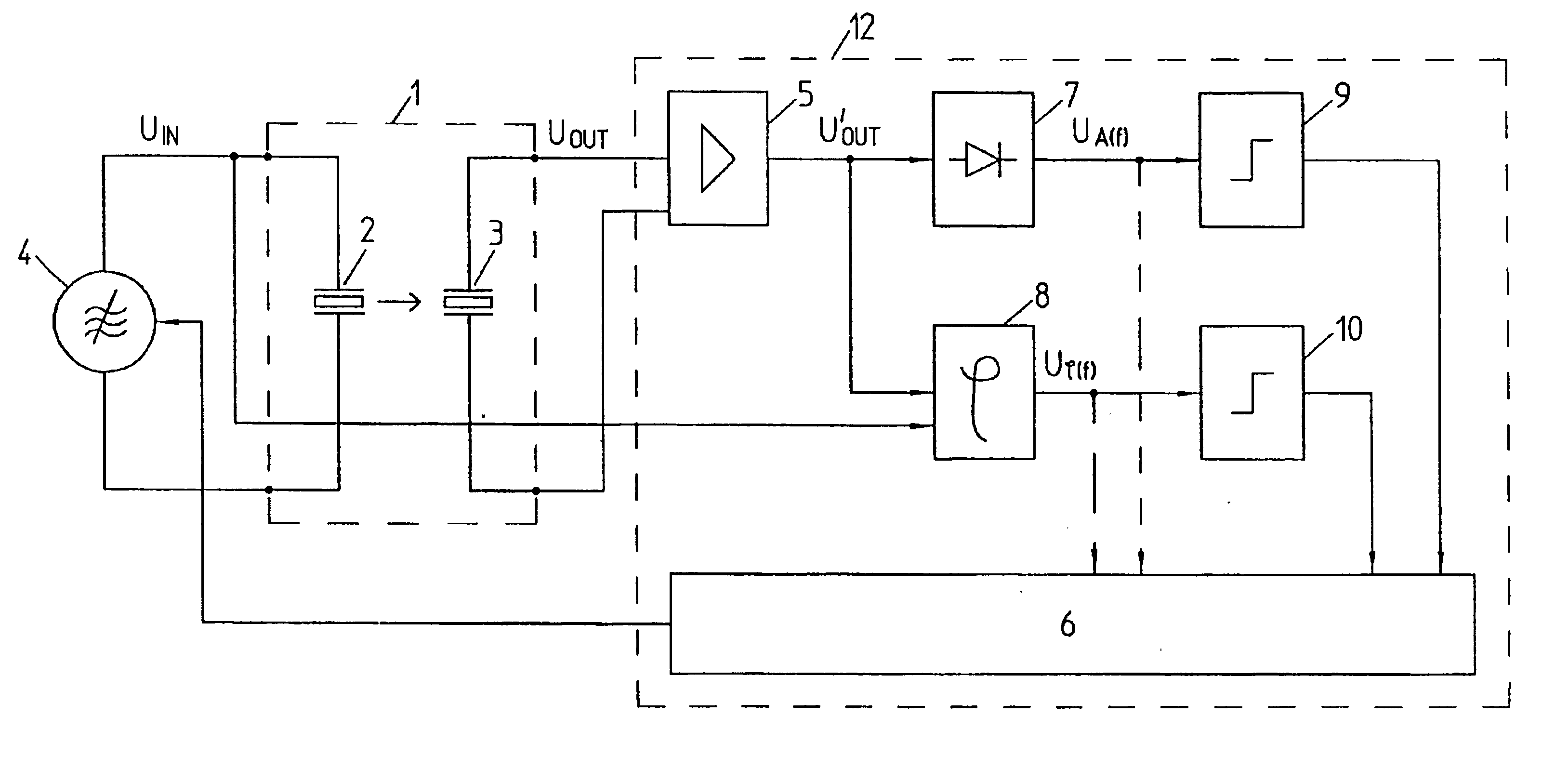
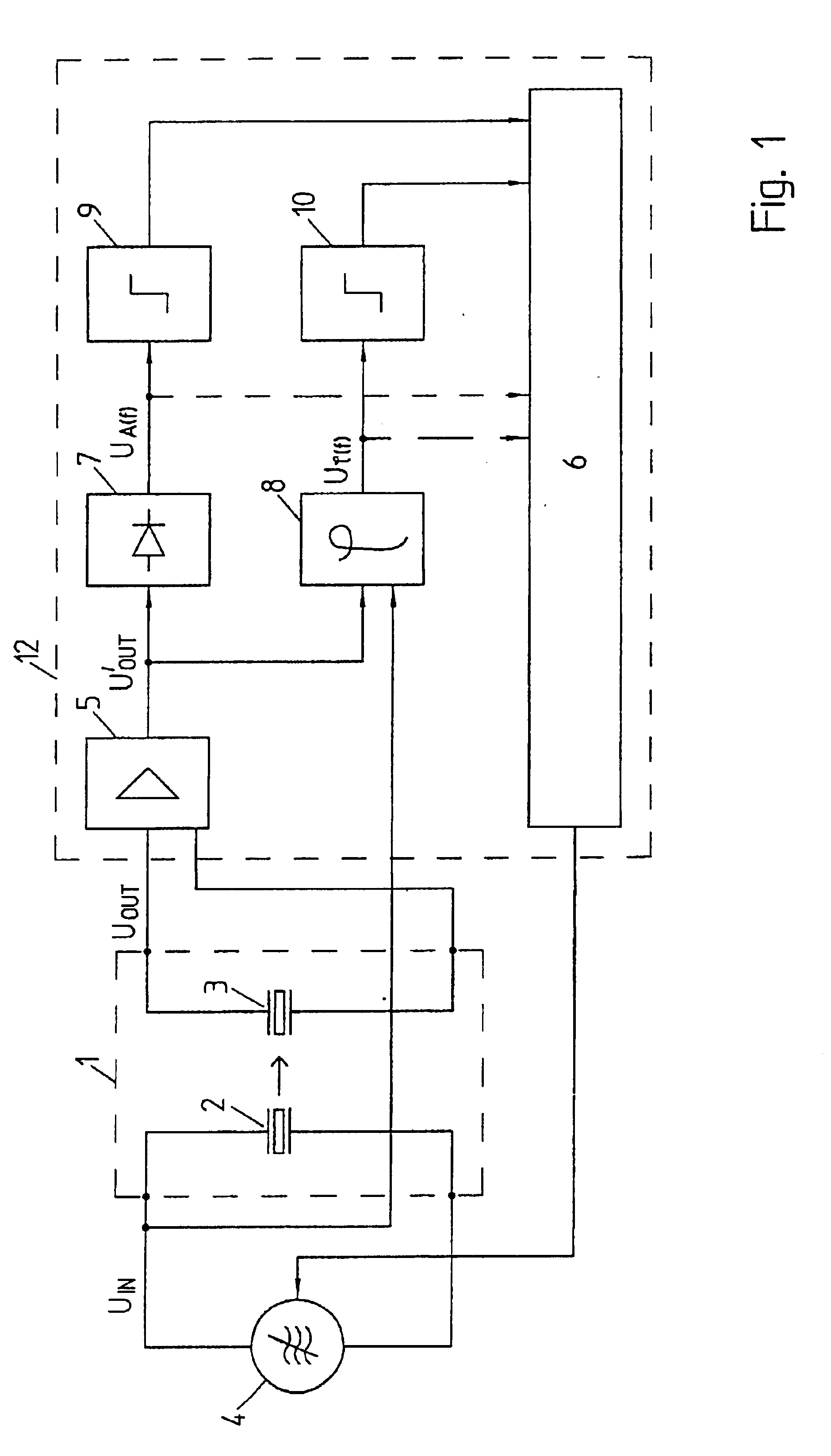
An electromechanical oscillating system 1 that contains separate excitation and detection elements 2, 3 and should be interpreted as an electrical quadrupole network is excited at the input poles with the voltage UIN of the AC voltage source 4. The mechanical vibratory element, which is realized in the form of a turning fork, e.g., and protrudes into the container is not explicitly shown in the figure. In this case, only the effect of the vibratory element as a coupling between the electromechanical vibratory elements 2, 3 is indicated in the form of an arrow. The voltage UOUT at the output of the quadrupole network is amplified by the amplifier 5.

The control, evaluation and output unit 6 continuously changes the frequency of the AC voltage source 4, which here is also referred to as a voltage-controlled oscillator VCO, over a certain range. The amplified output voltage Uout must be evaluated in order to obtain information on the operating state of the quadrupole network 1, i.e., co...


PUM


Abstract

The invention pertains to a method for determining and / or monitoring a predetermined level of a material in a container by means of a probe in the form of a vibrating rod that protrudes into the interior of the container and forms part of an electromechanical oscillating system. According to the invention, one or more characteristic parameters are measured after excitation of the system, where these parameters are taken into consideration in the evaluation of the measurement.

Description

FIELD OF THE INVENTIONThe invention pertains to a method for determining and / or monitoring a predetermined level of a material in a container according to the characteristics of the preamble of claim 1.BACKGROUND OF THE INVENTIONA level sensor for detecting a predetermined level is known from DE 3348119 C2. This sensor contains a probe in the form of a vibrating rod that protrudes into the container and is excited to vibrate by an electric excitation device. The frequency of the vibration depends on the level in the container. A vibratory system that is usually referred to as an oscillator is realized by amplifying and feeding back the electrically detected mechanical vibration signal to the excitation input.Similar methods and devices are described, for example, in DE 19720519 C2, EP 0985916 A1 and EP 0985917 A1. In all the aforementioned publications, the described vibratory level sensor contains, in principle, an electromechanical system that is excited to continuously self-oscil...

Claims


Application Information

Patent Timeline
IPC IPC(8): G01F23/296
CPCG01F23/2967
Inventor FEHRENBACH, JOSEF
Owner VEGA GRIESHABER GMBH & CO
Learn More