
Method for measuring the magnetic resonance (NMR) by means of spin echoes

a technology of spin echoes and magnetic resonances, applied in the field of nuclear magnetic resonance (nmr) spectroscopy or tomography, can solve problems such as signal loss, and achieve the effect of reducing the overall rf energy over the echo train

Inactive Publication Date: 2005-02-01
UNIVERSITATSKLINIKUM FREIBURG
View PDF10 Cites 21 Cited by
  • Summary
  • Abstract
  • Description
  • Claims
  • Application Information

AI Technical Summary

Benefits of technology

[0013]In contrast thereto, it is the object of the present invention to further improve a method of the above-described type such that the overall RF energy over the echo train is considerably reduced.
[0014]This object is achieved in accordance with the invention in a surprisingly simple and also effective fashion in that after reaching the initial PSS0 with respect to some refocusing flip angle α1 magnetization is transferred through gradual change of the refocusing flip angle in subsequent refocusing intervals to or close to the static pseudo steady state of the respectively used refocusing pulse with refocusing flip angle αn such that the echo amplitude of the nth echo, generated in this fashion, approaches the maximum possible value corresponding to the respective refocusing pulse with refocusing flip angle αn.

Problems solved by technology

Such an ideal flip angle can only be approximated in practice such that in particular for methods which are based on formation of many spin echoes, signal losses result on the basis of the deviation of the flip angle of the refocusing pulses of 180°.

Method used


Image

  • Method for measuring the magnetic resonance (NMR) by means of spin echoes
  • Method for measuring the magnetic resonance (NMR) by means of spin echoes
  • Method for measuring the magnetic resonance (NMR) by means of spin echoes

Examples


Embodiment Construction

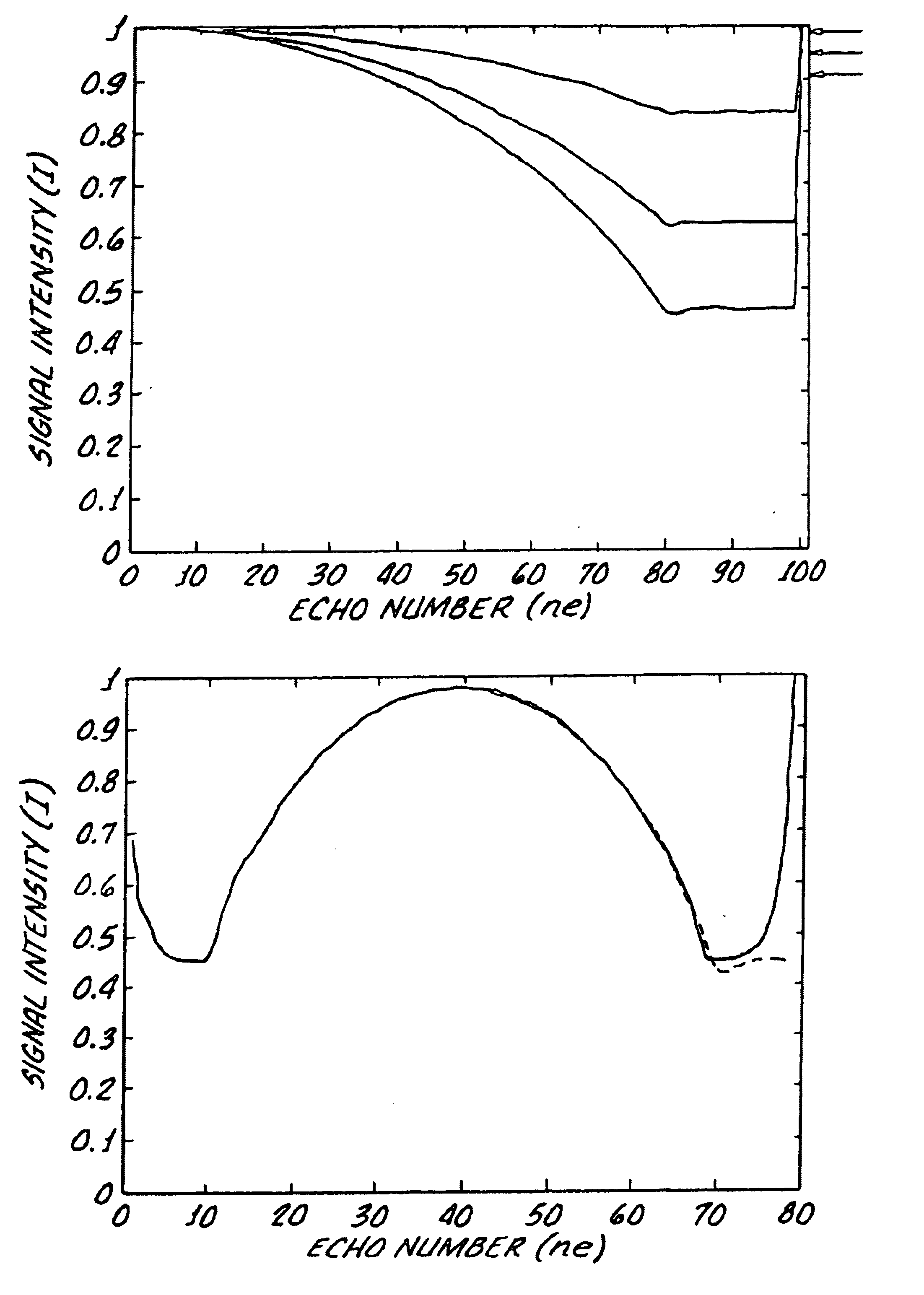
ntensities I along the echo number ne for a multi echo experiment wherein initially the refocusing flip angle is linearly reduced from 180° to 30° (1), 50° (2) and 90° (3) over the first 80 echoes, the final 90°+α / 2 pulse produces a signal of an intensity of 90% (1), 95% (2) and 99% (3);

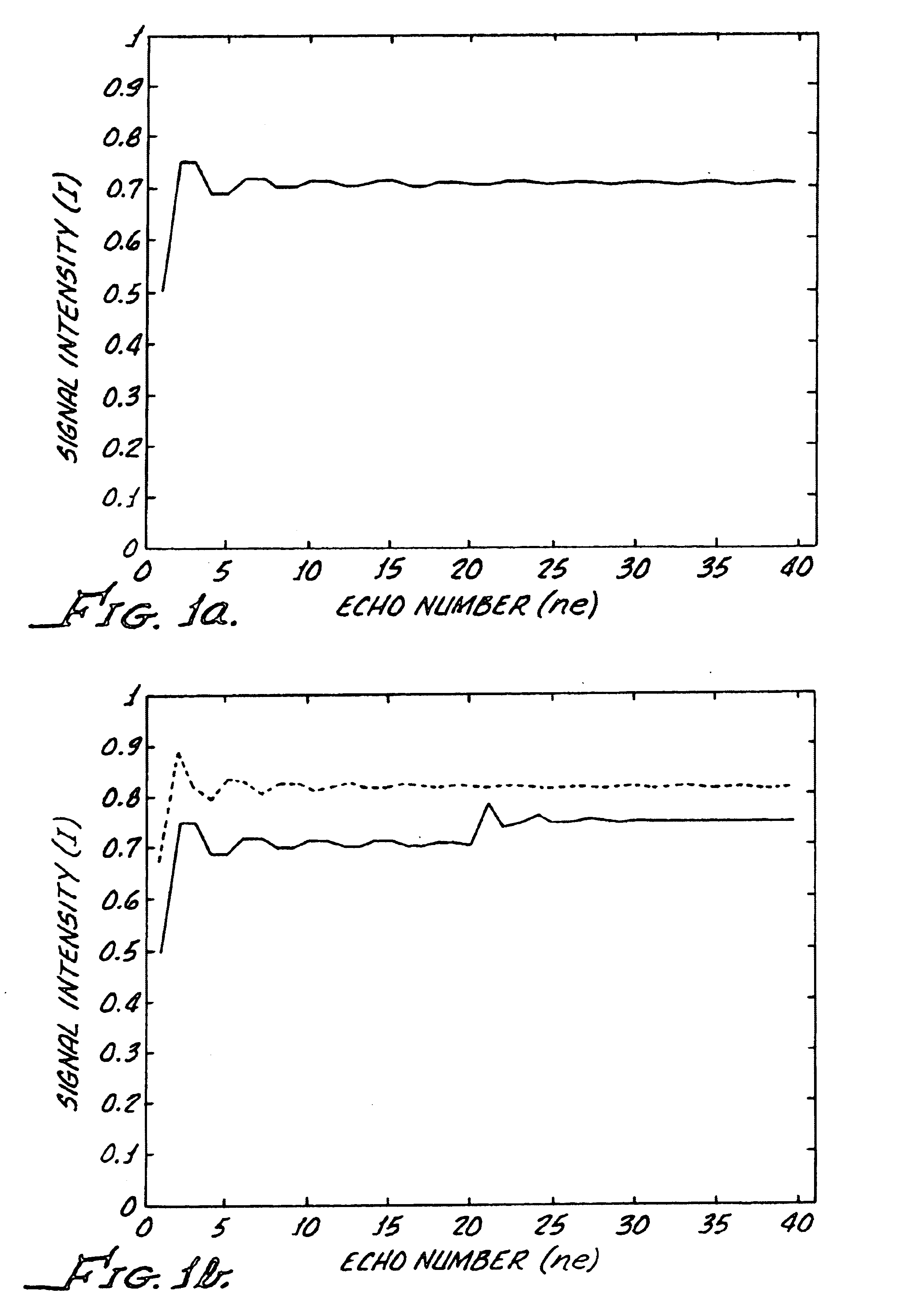
[0042]FIG. 12 shows signal intensities I along the echo number ne for a multi echo experiment wherein initially refocusing flip angles corresponding to those of FIG. 6b are used over the first 40 echoes, the second half of the echo train is carried out according to the principle of hyperecho formation;

[0043]FIGS. 13-14 compare flip angle (α) and signal intensity as a function of echo number (ne) for a prior art hyperecho experiment and an experiment in accordance with the present invention; and

[0044]FIGS. 15-16 compare the flip angle and signal intensity of a hyperecho sequence (dashed line) with a linear change in flip angle (dotted line) after the same initial sequence.

DESCRIPTION OF THE PREFERRED ...


PUM


Abstract

A nuclear magnetic resonance (NMR) spectroscopy or tomography method wherein a sequence of temporally mutually offset radio frequency (RF) pulses is applied onto a spin ensemble like a CPMG multi echo experiment, and wherein the magnetization produced after an initial excitation pulse is transferred to or close to the static pseudo steady state of the initially applied refocussing flip angle α1 is characterized in that magnetization is transferred through gradual change of the refocussing flip angle in subsequent refocussing intervals to or close to the static pseudo steady state of the respectively used refocussing pulse with refocussing flip angle αn such that the echo amplitude of the nth echo generated in this fashion approaches the maximum possible value corresponding to the respective refocussing pulse with refocussing flip angle αn. The RF energy required for excitation of the nuclear spins can thereby be considerably reduced without having to accept signal intensity losses.

Description

[0002]This application claims Paris Convention priority of DE 101 58 531.4 filed 29 Nov. 2001 the complete disclosure of which is hereby incorporated by reference.BACKGROUND OF THE INVENTION[0003]The invention concerns a method of nuclear magnetic resonance (NMR) spectroscopy or tomography, wherein a sequence of radio frequency (RF) pulses consisting of an excitation pulse followed by a sequence of in general equidistant refocusing pulses is applied to a spin ensemble like in a CPMG multi echo experiment, and wherein the magnetization generated after an initial excitation pulse is transferred to or close to the static pseudo steady state of some refocusing flip angle α1 and kept in or close to the static pseudo steady state of any ensuing refocusing pulse αn.[0004]The basic spin echo refocusing experiment is known from Hahn E L, Spin Echoes, Phys. Rev. 80:580-594 (1950) (=Reference [1]).[0005]Nuclear resonance signals are often measured through the spin echo method [1]. Therein, the...

Claims


Application Information

Patent Timeline
IPC IPC(8): G01R33/561G01R33/54
CPCG01R33/5613
Inventor HENNIG, JURGEN
Owner UNIVERSITATSKLINIKUM FREIBURG
Learn More