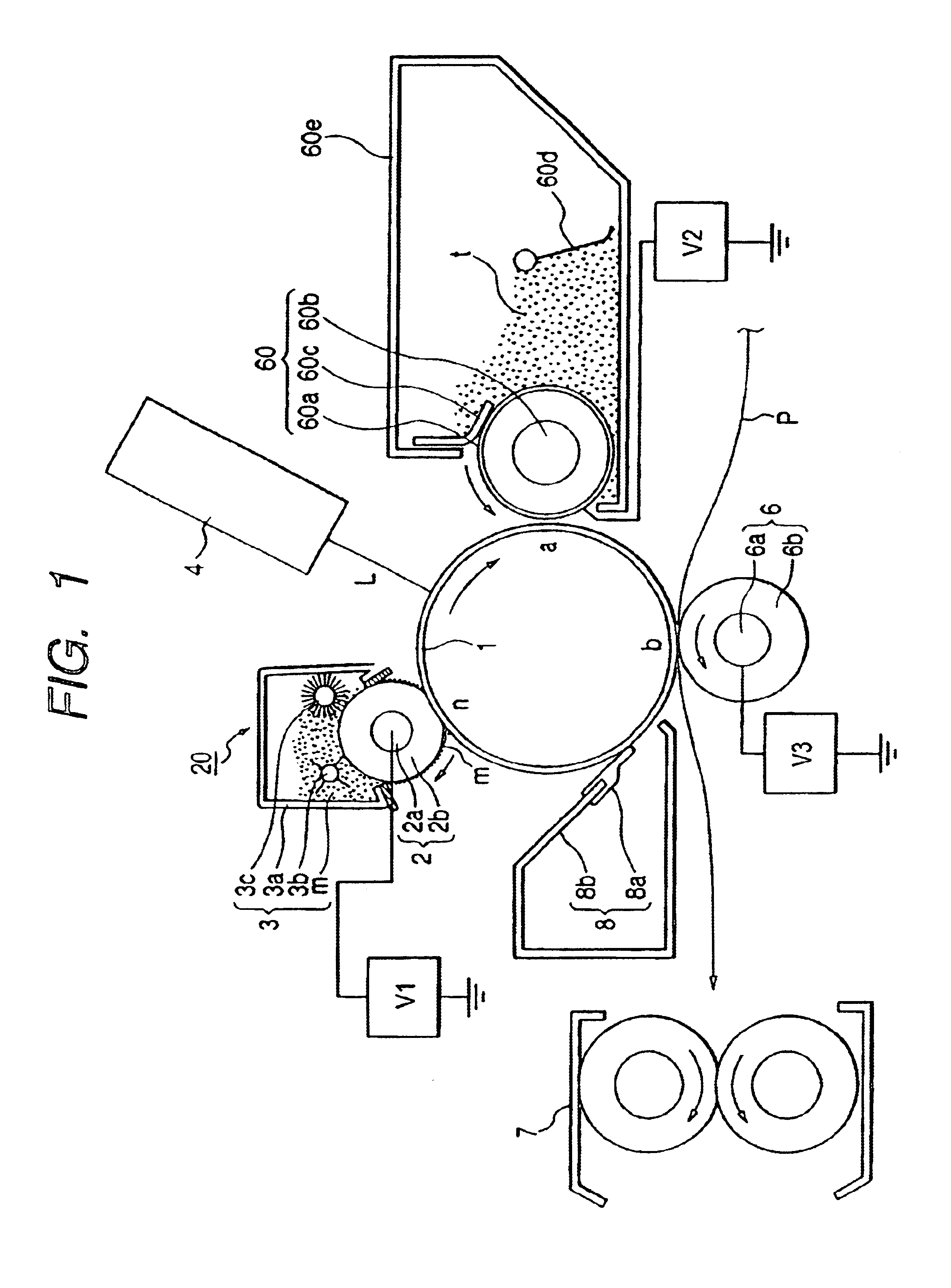
Charging member and image forming apparatus provided with the same

Inactive Publication Date: 2005-01-25
CANON KK
View PDF17 Cites 11 Cited by
  • Summary
  • Abstract
  • Description
  • Claims
  • Application Information

AI Technical Summary

Benefits of technology

It is an object of the present invention to provide a charging member and an image forming apparatus which improve the non-uniformity of a halftone image peculiar to particle charging.
It is another object of the present invention to provide a charging member and an image forming apparatus which improve fog peculiar to particle charging.
It is another object of the present invention to provide a charging member and an image forming apparatus which reduce the cohesiveness of electrically conductive particles.
It is another object of the present invention to provide an image forming apparatus which is suited for collecting a developer by a developing device by preventing the cohesion of electrically conductive particles coming off a charging member.

Problems solved by technology

Also, the roller charging by discharging is high in applied voltage and if there is a pinhole (the exposure of a substrate by the injury of the film of the member to be charged), a voltage drop will spread to even the periphery thereof and faulty charging will occur.
As a form of the contact charging member used in the direct injecting type charging apparatus, an attempt by a charging roller for discharging or the like has been made, but direct injecting type charging has been impossible by the charging roller for discharging.
In the conventional charging technique as described above, however, it has become apparent that the image recording apparatus causes the following deterioration of the quality of image.
Firstly, the problem of the uniformity of a halftone image.
Further, there has occurred a faulty image having its ground slightly developed, i.e., fog.

Method used


Image

  • Charging member and image forming apparatus provided with the same
  • Charging member and image forming apparatus provided with the same
  • Charging member and image forming apparatus provided with the same

Examples


example 1

(2) Example 1

In the image forming apparatus according to Embodiment 1, particles m having a particle diameter of 1.3 μm and a degree of cohesion of 60% is used as the charging particles m, and the application of the particles to the charging roller 2 is effected by the charging particle supplying device 3.

example 2

(4) Example 2

This is the image forming apparatus according to Embodiment 2. As the charging particles m, use was made of particles subjected to silane coupling treatment (shown as treatment A in an evaluation result table) using n-bytyltrimethoxy silane as a treating agent. Also, the amount of treatment thereof was 1 weight % relative to the charging particles. Particles m having a particle diameter of 1.3 μm and a degree of cohesion of 85% were used as the charging particles, and about 1 weight % of them was added to the developer.

example 3

(5) Example 3

In the image forming apparatus according to Embodiment 2, as the charging particles m, use was made of particles m having a particle diameter of 1.3 μm and a degree of cohesion of 60% and subjected to treatment similar to that in Example 2 with an amount of treatment of 1.8 weight % for charging particles, and about 1 weight % of them was added to the developer.

(6) Comparative Example 3

In the image forming apparatus according to Embodiment 2, as the charging particles m, use was made of conventional particles having a particle diameter of 1.8 μm and a high degree of cohesion of 89%, and about 1 weight % of them was added to the developer.


PUM


Abstract

A charging member for charging a member to be charged and an image forming apparatus provided with the same have electrically conductive particles and an electrically conductive particle bearing member having elasticity and bearing the electrically conductive particles thereon, and the degree of cohesion of the electrically conductive particles is 0.1 to 85%. Thereby, the non-uniformity of a halftone image peculiar to particle charging can be improved.

Description

BACKGROUND OF THE INVENTION1. Field of the InventionThis invention relates to a charging member for charging a member to be charged. The invention also relates to an image forming apparatus such as a copying machine or a printer in which a charging member is brought into contact with a member to be charged to thereby charge the surface of the member to be charged.2. Related Background ArtHeretofore, a contact charging apparatus has been one in which an electrically conductive charging member (a contact charging member or a contact charger) of a roller type (charging roller), a fur brush type, a magnetic brush type, a blade type or the like is brought into contact with a member to be charged such as an image bearing member, and a predetermined charging bias is applied to this contact charging member to thereby charge the surface of the member to be charged to a predetermined polarity and potential.These charging apparatuses are expressed together as a contact charging apparatus, but ...

Claims


Application Information

Patent Timeline
IPC IPC(8): G03G15/02G03G15/08
CPCG03G15/0216
Inventor CHIGONO, YASUNORIOKUDA, KOICHISHIMIZU, YASUSHIYOSHIDA, MASAHIRO
Owner CANON KK
Why Eureka
Try Eureka