
Variable blazed grating

a blazed grating, variable technology, applied in the field of communication systems, can solve the problems of large required drive voltage, additional system components, slow device operation, etc., to facilitate optical signal processing, reduce or eliminate at least, and facilitate high-speed optical signal processing

Inactive Publication Date: 2005-01-25
CHEETAH OMNI
View PDF99 Cites 23 Cited by
  • Summary
  • Abstract
  • Description
  • Claims
  • Application Information

AI Technical Summary

Benefits of technology

"The present invention provides a method and apparatus for economically facilitating high speed optical signal processing. It uses a diffraction-based technology to process optical signals with good contrast ratios without requiring additional beam collection and combining technology. The invention includes an inner conductive layer and a plurality of at least partially reflective mirror strips that can rotate to diffract the input optical signal. The narrow strips used in the invention allow for a wide range of blaze angles, reducing the required drive voltage and increasing the resolution of the output signal. The flexible operation of the invention makes it suitable for various signal processing applications, and the cost-effectiveness of the invention allows for the fabrication of arrays of variable blazed-grating based elements at a reduced cost compared to producing a single element. This invention provides significant cost savings in processing signals carrying information on multiple channels or wavelengths."

Problems solved by technology

This approach suffers from a number of deficiencies.
This results in difficulties maintaining two substantially equal outputs, because only a small portion of the diffracted signal can be recovered using a single detector or a single fiber.
This approach typically results in additional system components, complexity and cost.
The combination of a large area membrane and a confining supporting material generally resulted in slow device operation and large required drive voltages.
The large width of the slats severely limits the blaze angle (less than two degrees) that can be obtained using this approach.
In addition, the width of the slats significantly limits the frequency at which these devices can change states, and increases the drive voltage necessary to rotate the slats.

Method used


Image

  • Variable blazed grating
  • Variable blazed grating
  • Variable blazed grating

Examples


Embodiment Construction

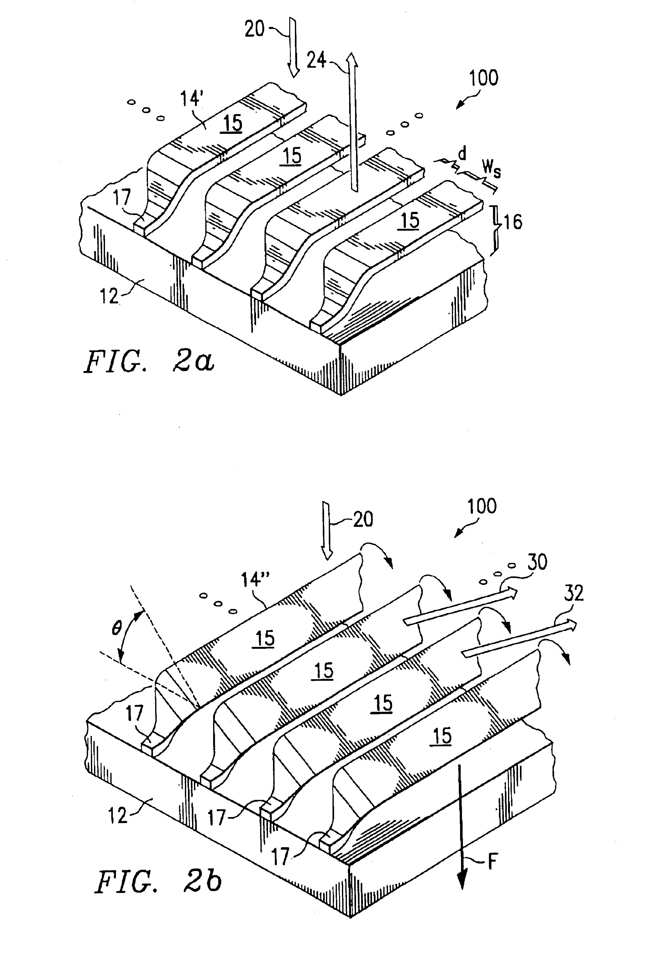
Generally, a variable blazed grating device is an element having a diffraction grating that can be selectively displaced relative to an incoming optical signal, with the result that the majority of the diffracted portions of the optical signal are communicated in one direction. One aspect of the present invention relates to a novel configuration of a variable blazed grating device.

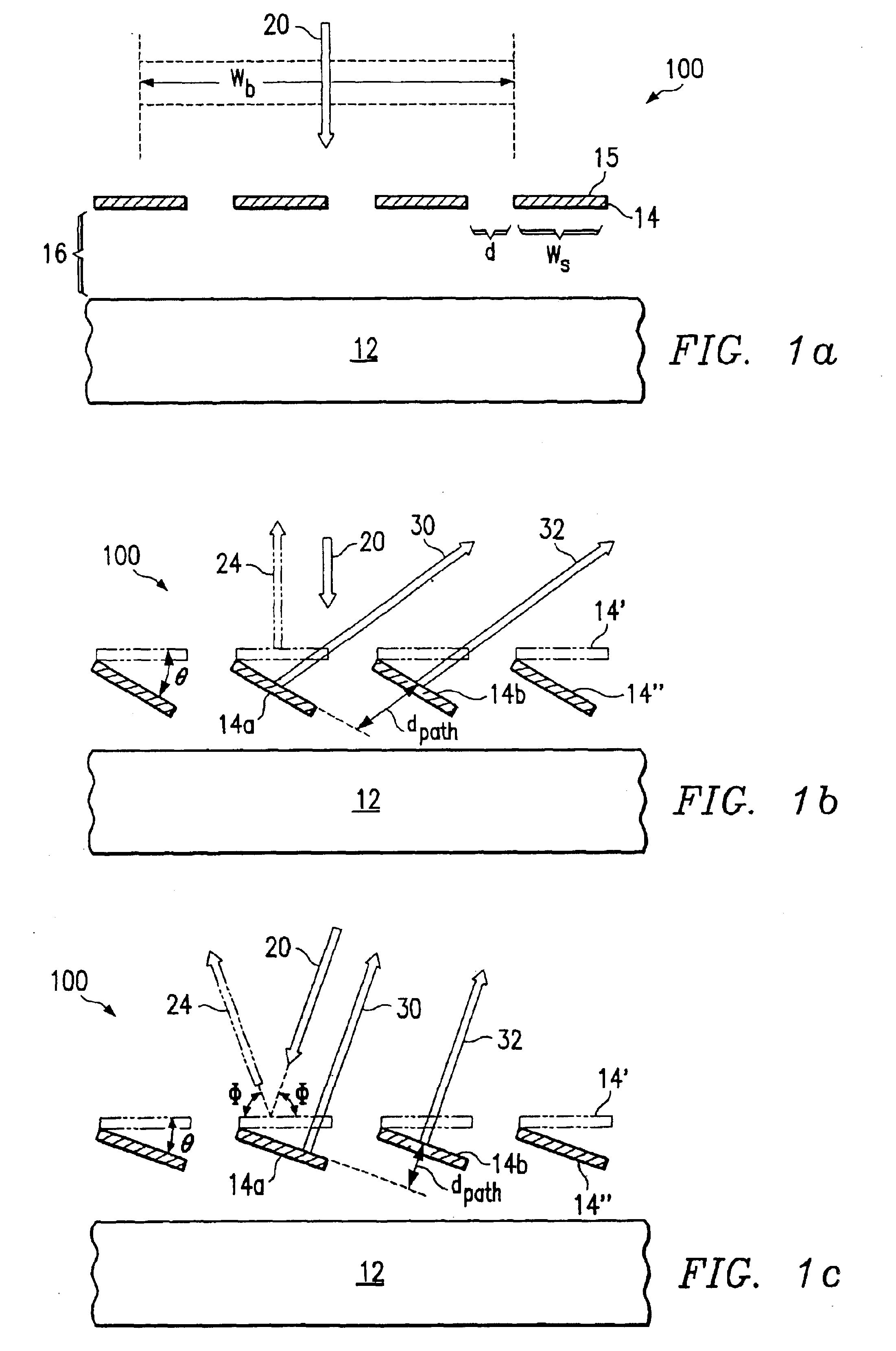
FIG. 1a shows a cross-section view of one exemplary embodiment of a variable blazed grating-based apparatus 100 operable to facilitate high speed optical signal processing. Throughout this document, the term “signal processing” includes attenuation, switching, phase shifting, or any other manipulation of one or more optical signals.

In this example, apparatus 100 includes a substrate 12 and a plurality of strips 14 disposed outwardly from substrate 12. In a particular embodiment, substrate 12 comprises a semiconductor substrate formed, for example, from silicon. Other materials could be used for substrate 1...


PUM


Abstract

In one aspect of the invention, an apparatus operable to provide optical signal processing includes an inner conductive layer including an at least substantially conductive material and a plurality of at least partially reflective mirror strips disposed outwardly from the inner conductive layer and operable to receive an input optical signal, wherein none of the plurality of strips has a width greater than 40 microns. At least some of the strips are operable to undergo a partial rotation in response to a control signal, the partial rotation resulting in a diffraction of the input optical signal wherein a majority of the diffracted input signal is communicated in one direction.

Description

TECHNICAL FIELD OF THE INVENTIONThe present invention relates to the field of communication systems, and more particularly to an apparatus and method operable to facilitate signal processing using variable blazed grating based elements.BACKGROUND OF THE INVENTIONAs optical systems continue to increase the volume and speed of information communicated, the need for methods and apparatus operable to facilitate high speed optical signal processing also escalates. Various devices and methodologies have been developed to provide numerous signal processing capabilities on optical signals. Some of these devices attempt to control a diffraction of an input optical signal to facilitate basic signal processing functions.One such approach uses an optical switching device having a plurality of adjacent reflective strips disposed above a conductive inner surface. In one state of operation, the adjacent reflective strips remain in a single plane and substantially reflect optical signals received. ...

Claims


Application Information

Patent Timeline
Patent Type & Authority Patents(United States)
IPC IPC(8): G02B26/08G02B6/34
CPCG02B6/12009G02B6/2932G02B26/0808G02B6/29322Y10S359/90
Inventor ISLAM, MOHAMMED N.KUDITCHER, AMOS
Owner CHEETAH OMNI
Learn More