
System and method for sending high fidelity sound between wireless units

a wireless unit and wireless technology, applied in the field of wireless communication, can solve the problems of not being able to provide a wireless technology with high fidelity, many voice recognition systems require high fidelity sound, etc., and achieve the effect of reducing or eliminating at least high fidelity sound

Inactive Publication Date: 2007-01-02
HEWLETT PACKARD DEV CO LP
View PDF7 Cites 12 Cited by
  • Summary
  • Abstract
  • Description
  • Claims
  • Application Information

AI Technical Summary

Benefits of technology

[0005]The present invention provides systems and methods that substantially reduce or eliminate at least some of the disadvantages associated with previous systems and methods for sending audible sound between wireless units. Accordingly, the present invention provides systems and methods for sending high fidelity sound between wireless units.
[0008]The present invention has several technical advantages. For example, the present invention allows high fidelity sound to be sent between wireless units. Thus, a second wireless unit may respond to audible commands received at a first wireless unit. Furthermore, high fidelity music may be sent from one wireless unit to another wireless unit. As another example, in certain embodiments, high fidelity sound may be exchanged between two wireless units. Accordingly, a wireless unit that is sending high fidelity sound may also receive high fidelity sound. This may be useful for allowing the exchange of audible commands and / or conversation between wireless units. As a further example, in certain embodiments, two analog signals representing the audible sounds are created, which allows for improved noise cancellation from the audible sounds. Of course, different embodiments of the invention may have none, one, some, or all of these technical advantages and / or additional technical advantages.

Problems solved by technology

Unfortunately, many voice recognition systems require higher fidelity sound than can be provided by an eight kilohertz sample rate using eight bit representations.
Accordingly, these systems may not be available in this wireless technology.

Method used


Image

  • System and method for sending high fidelity sound between wireless units
  • System and method for sending high fidelity sound between wireless units
  • System and method for sending high fidelity sound between wireless units

Examples


Embodiment Construction

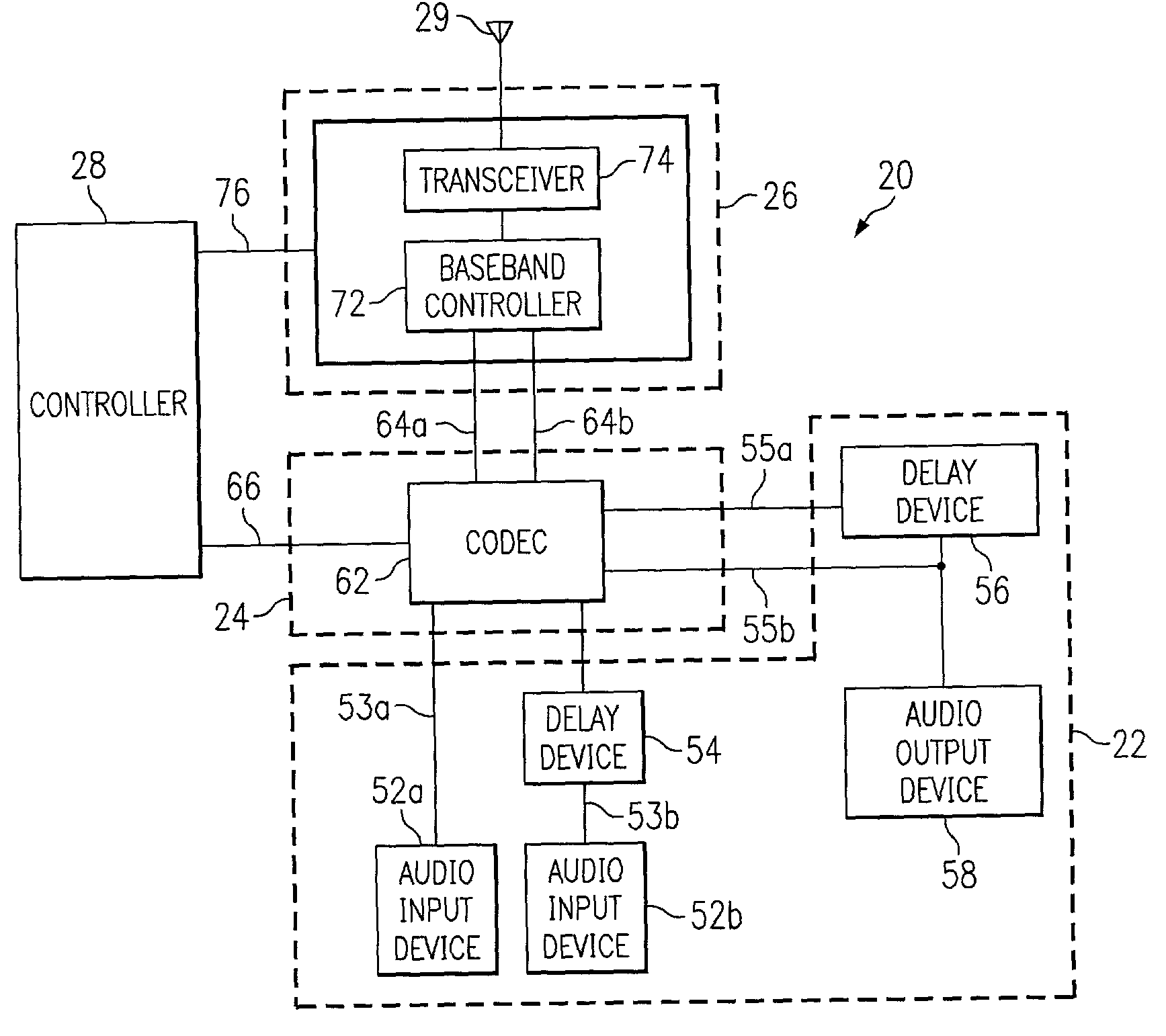
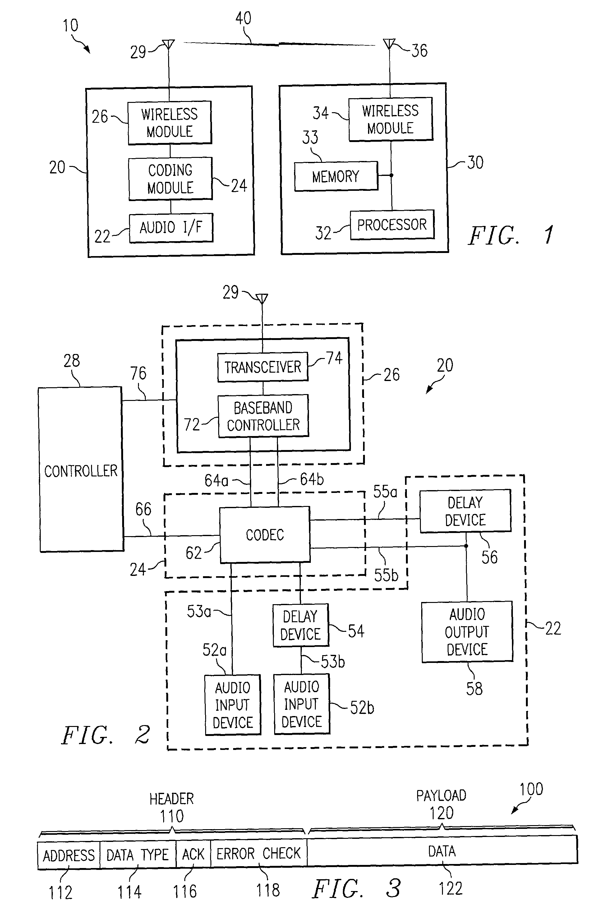
[0016]FIG. 1 illustrates a system 10 for sending high fidelity sound between wireless units in accordance with one embodiment of the present invention. As illustrated, system 10 includes a wireless unit 20 and a wireless unit 30, which may or may not be mobile. In general, wireless unit 20 transmits data, including data representing high fidelity sound, to wireless unit 30 over a wireless link 40, and wireless unit 30 receives the data and processes it according to its type. As used herein, high fidelity sound means audible sound representations that contain samples at greater than approximately eight kilohertz. In other embodiments, system 10 may include additional wireless units.

[0017]In more detail, wireless unit 20 includes an audio interface 22, a coding module 24, a wireless module 26, and an antenna 29. Audio interface 22 is operable to receive audible sounds from a user of wireless unit 20 and generate signals that represent the audible sounds. Note that audio interface 22 c...


PUM


Abstract

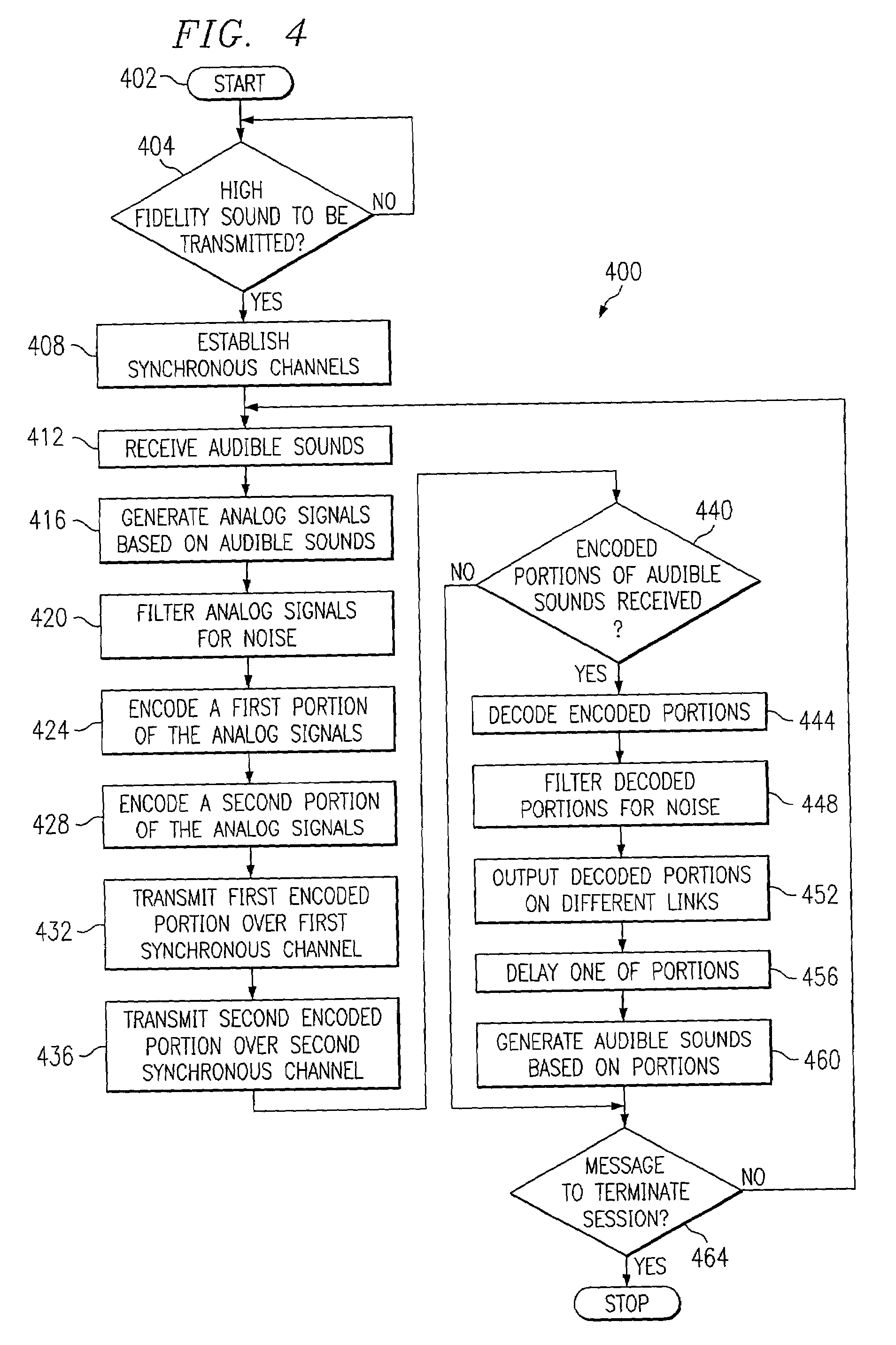
A system and method for sending high fidelity sound between wireless units include the capability to receive audible sounds at a wireless unit and generate signals that represent the audible sounds. The system and method also include the capability to encode a first portion of the signals and encode a second portion of the signals. The system and method further include the capability to transmit the first encoded portion over a first synchronous channel and transmit the second encoded portion over a second synchronous channel.

Description

TECHNICAL FIELD OF THE INVENTION[0001]This invention relates generally to wireless communications and, more particularly, to a system and method for sending sound between wireless units.BACKGROUND OF THE INVENTION[0002]Wireless technologies have the ability to allow data transfer between electronic devices without requiring that the devices be physically coupled together. Accordingly, in today's highly mobile world, using wireless technologies for data transfer is increasingly desirable so that electronic devices can interact with each other without a user having to take the time to physically couple them together or having to transport the proper couplings.[0003]Several short-range wireless technologies are currently under development to accomplish this goal. One such technology that has received considerable interest in the wireless community is known as Bluetooth™. Bluetooth™ technology proposes to use a one megabit per second wireless link that is operable over a distance of app...

Claims


Application Information

Patent Timeline
Patent Type & Authority Patents(United States)
IPC IPC(8): H04B1/38H04B1/18G10L19/00G10L19/008G10L19/02H04B7/26H04H20/88H04H60/80H04L12/28H04L12/56
CPCH04H20/88H04H60/80H04W92/18
Inventor THAYER, PETER A.HORAN, DALE J.SHLAYEN, LEONID
Owner HEWLETT PACKARD DEV CO LP
Learn More