
Digital television receiver

a digital television and receiver technology, applied in the field of digital television receivers, can solve problems such as picture quality degradation, analog-type tvs exposed various kinds of problems, and unidirectional medium limitations of analog-type tvs

Inactive Publication Date: 2005-01-25
LG ELECTRONICS INC
View PDF3 Cites 14 Cited by
  • Summary
  • Abstract
  • Description
  • Claims
  • Application Information

AI Technical Summary

Benefits of technology

Accordingly, the present invention is directed to a digital television receiver that substantially obviates one or more problems due to limitations and disadvantages of the related art.

Problems solved by technology

However, such analog-type TVs have exposed various kinds of problems as they become large-sized and have high-grade functions.
First, in case of viewing the existing analog-type broadcasts such as an NTSC, PAL, or SECAM type through a large-sized TV, it can be known from experience that the picture quality deteriorates.
Second, the number of serviceable broadcasting channels in a channel range of both a very high frequency and an ultra high frequency, which are currently allocated to the TV broadcasts, is limited to about 80, and the number of actually useable ground wave channels is only a half thereof due to the interference among adjacent channels.
Third, the analog-type TV has limitations of a unidirectional medium.
Last, the market for analog TVs is at its peak of congestion.
However, in order to change the current analog ground wave broadcasting system to the digital ground wave broadcasting system, all the broadcasting equipment and TVs should be changed, and this requires a lot of time.
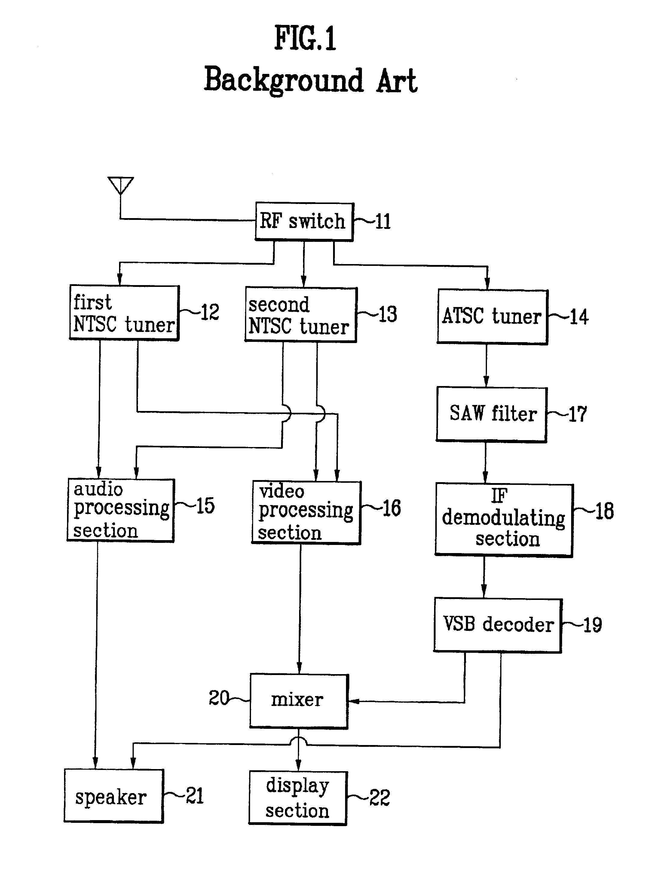
As a result, the conventional digital TV that has the main / sub picture function requires three tuners including two analog tuners and one digital tuner, and this causes the manufacturing cost of the TV to be increased.

Method used


Image

  • Digital television receiver
  • Digital television receiver
  • Digital television receiver

Examples


Embodiment Construction

Reference will now be made in detail to the preferred embodiments of the present invention, examples of which are illustrated in the accompanying drawings.

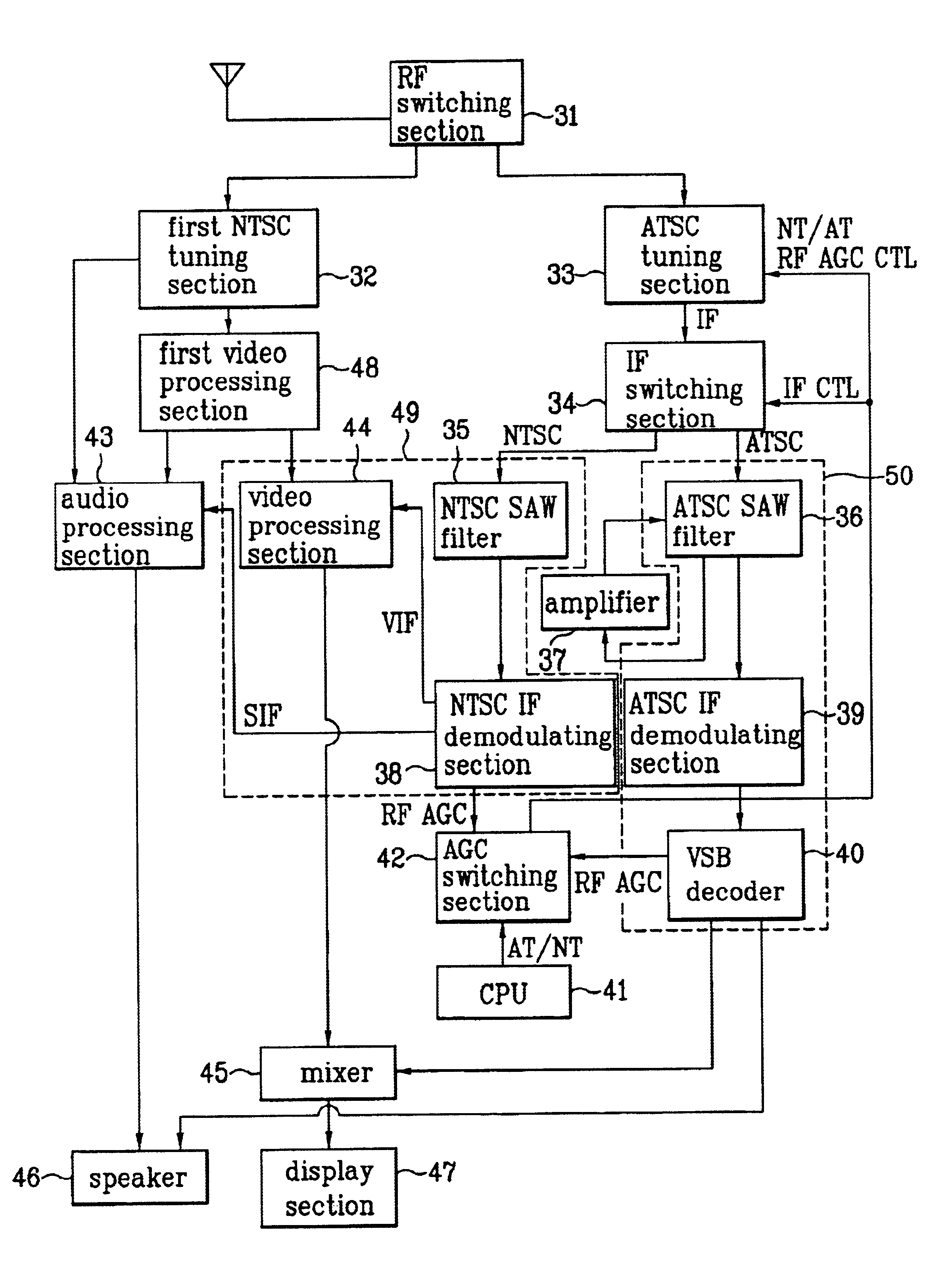
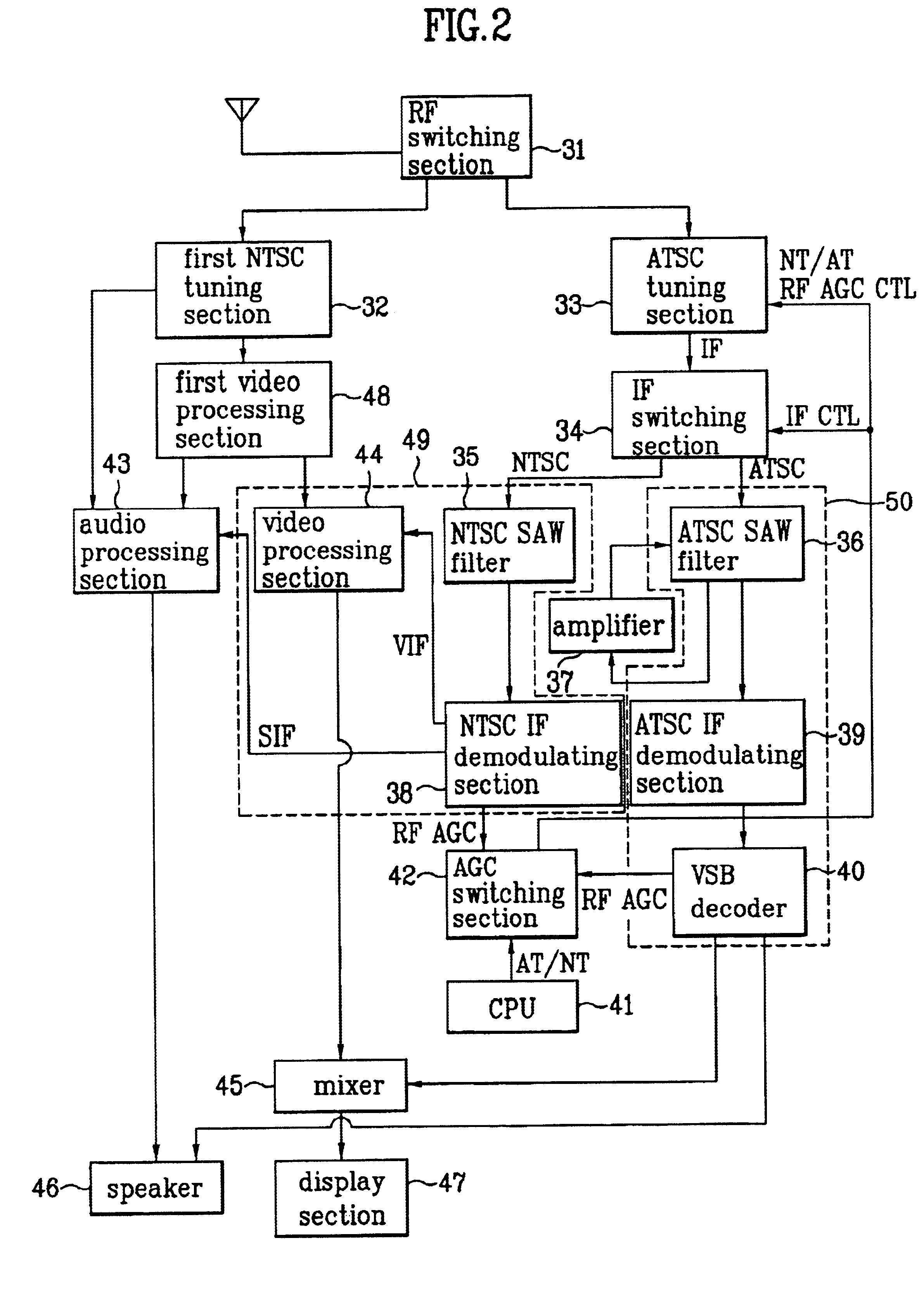
FIG. 2 is block diagram illustrating the construction of a digital television receiver according to the present invention.

Referring to FIG. 2, the digital television receiver (TV) according to the present invention includes a CPU 41 that is a control section for generating and outputting control signals according to a user's selection of a channel and a main / sub picture, an RF switching section 31 for being switched under the control of the CPU 41, and selecting and outputting to a specified tuner an RF signal received through an antenna, an NTSC tuning section 32 for tuning an NTSC broadcasting signal of a channel selected by the user among RF signals outputted through the RF switching section 31, demodulating the tuned signal into an intermediate frequency (IF) signal, and then separating the IF signal into a video IF (VIF) sign...


PUM


Abstract

A digital television receiver that can perform analog / digital and main / sub picture functions only using an analog tuner and an analog / digital-combined tuner is disclosed. The digital television receiver includes a control section for generating and outputting control signals according to a user's command for selecting a channel and a main / sub picture, an analog tuning section for selecting an RF signal of an analog channel selected by the user among RF signals received through an antenna under the control of the control section, and converting the selected RF signal into an IF signal, and an analog / digital (A / D)-combined tuning section for selecting an RF signal of an analog or digital channel selected by the user among the RF signals received through the antenna under the control of the control section. The main and sub pictures can be constructed using only two tuners irrespective of the analog / digital channels, and thus the manufacturing cost can be reduced with the improvement of the product competitiveness.

Description

BACKGROUND OF THE INVENTION1. Field of the InventionThe present invention relates generally to a television receiver, and more particularly, to a digital television receiver (TV) that can receive both an analog video signal and a digital video signal.2. Background of the Related ArtUp to now, diverse types of analog TVs from small-sized models of 14 inches to projection TVs of over 60 inches have been presented to consumers.However, such analog-type TVs have exposed various kinds of problems as they become large-sized and have high-grade functions.First, in case of viewing the existing analog-type broadcasts such as an NTSC, PAL, or SECAM type through a large-sized TV, it can be known from experience that the picture quality deteriorates.Second, the number of serviceable broadcasting channels in a channel range of both a very high frequency and an ultra high frequency, which are currently allocated to the TV broadcasts, is limited to about 80, and the number of actually useable grou...

Claims


Application Information

Patent Timeline
Patent Type & Authority Patents(United States)
IPC IPC(8): H04N5/46H04N5/45H04N5/44H04N11/00
CPCH04N5/4446H04N5/46H04N5/45H04N5/4401H04N11/002H04N21/426H04N21/42638H04N21/4316H04N21/4383H04N11/24
Inventor MIN, KI TAE
Owner LG ELECTRONICS INC
Learn More