Laser illuminating apparatus for illuminating a strip-shaped or linear area

a technology of linear area and illuminating apparatus, which is applied in the direction of lasers, instruments, optical resonator shape and construction, etc., can solve the problems of unfavorable light emitted by light-emitting diodes, assembly is not suitable for illuminating linear or strip-shaped areas, and large loss of light, so as to achieve high output power and high radiant power , the effect of personal eye protection

Inactive Publication Date: 2005-01-18
GIESECKE & DEVRIENT GMBH
View PDF16 Cites 7 Cited by
  • Summary
  • Abstract
  • Description
  • Claims
  • Application Information

AI Technical Summary

Benefits of technology

The invention is based on the problem of stating a laser illuminating apparatus for illuminating a strip-shaped or linear area of an object that permits strong illumination of the area to be illuminated with laser light, is characterized by low losses and furthermore guarantees the required personal eye protection.
First, the inventive laser illuminating apparatus spatially fans out the laser light generated by a laser light source in two mutually orthogonal directions to form a laser light beam fan. By an astigmatic lens having a small focal length in comparison to its distance from the origin of the laser light beam fan, said laser light beam fan is disposed with respect to the area to be illuminated so as to achieve linear or striped illumination in said area. The relatively small focal length of the astigmatic lens, which is formed in particular as a grid rod lens, causes the area to be illuminated to be disposed relatively near said astigmatic lens, and with increasing distance from the focal plane of the astigmatic lens the laser beam bundle diverges at a very large divergence angle. A large divergence angle means that any observer in this area will be confronted with relatively low power density of the laser beams.
The formation of the laser light beam fan is preferably likewise obtained with an astigmatic lens, so that for example two mutually orthogonal rod lenses are disposed at a relatively great distance—based on their focal lengths—in the output beam path of the laser. Such an assembly of two astigmatic lenses permits an extremely simple structure while simultaneously guaranteeing the required eye protection for any observers. Corresponding geometrical arrangement and selection of the lenses permits the total laser light to pass through the lenses, which avoids losses. Additional measures to permit total laser light to pass through the lens may be taken to obtain a further reduction of losses.
The inventive measures make it possible to use a laser light source with high output power, thereby achieving—with the further help of measures for containing losses—high radiant power in the area to be illuminated. Since the laser light is extremely narrow-band it is especially suitable for carrying out spectroscopic examinations of for example bank notes and the like. Furthermore, personal eye protection is guaranteed despite the high laser power, since the laser light cannot be focused on a point of the retina but only on a line of the retina due to the astigmatic lens assembly (astigmatism=not converging to a point). This avoids pointwise high power densities on the retina. It is thus possible to increase the power to several hundred megawatts e.g. while heeding the standard DIN EN 60825 in laser class 3a permitting only few megawatts. Corresponding selection of the components and geometrical arrangement geometrical arrangement make it possible to obtain line or strip widths of under 0.5 millimeters.

Problems solved by technology

Specifically for spectroscopic examination, however, the light emitted by light-emitting diodes is unfavorable since the light is broadband.
However, the fiber optics involves a complex structure and furthermore leads to considerable loss of light.
Such an assembly is not suitable for illuminating linear or strip-shaped areas, however.
The large-large-surface cylindrical Fresnel lenses involve considerable losses of light in the range of 30-70% of the laser power.
To guarantee personal eye protection, however, restrictive power limitations must be heeded, that is, only relatively low laser powers may be used or special saftety measures must be taken that make the overall system complicated and elaborate.

Method used


Image

  • Laser illuminating apparatus for illuminating a strip-shaped or linear area
  • Laser illuminating apparatus for illuminating a strip-shaped or linear area

Examples


Embodiment Construction

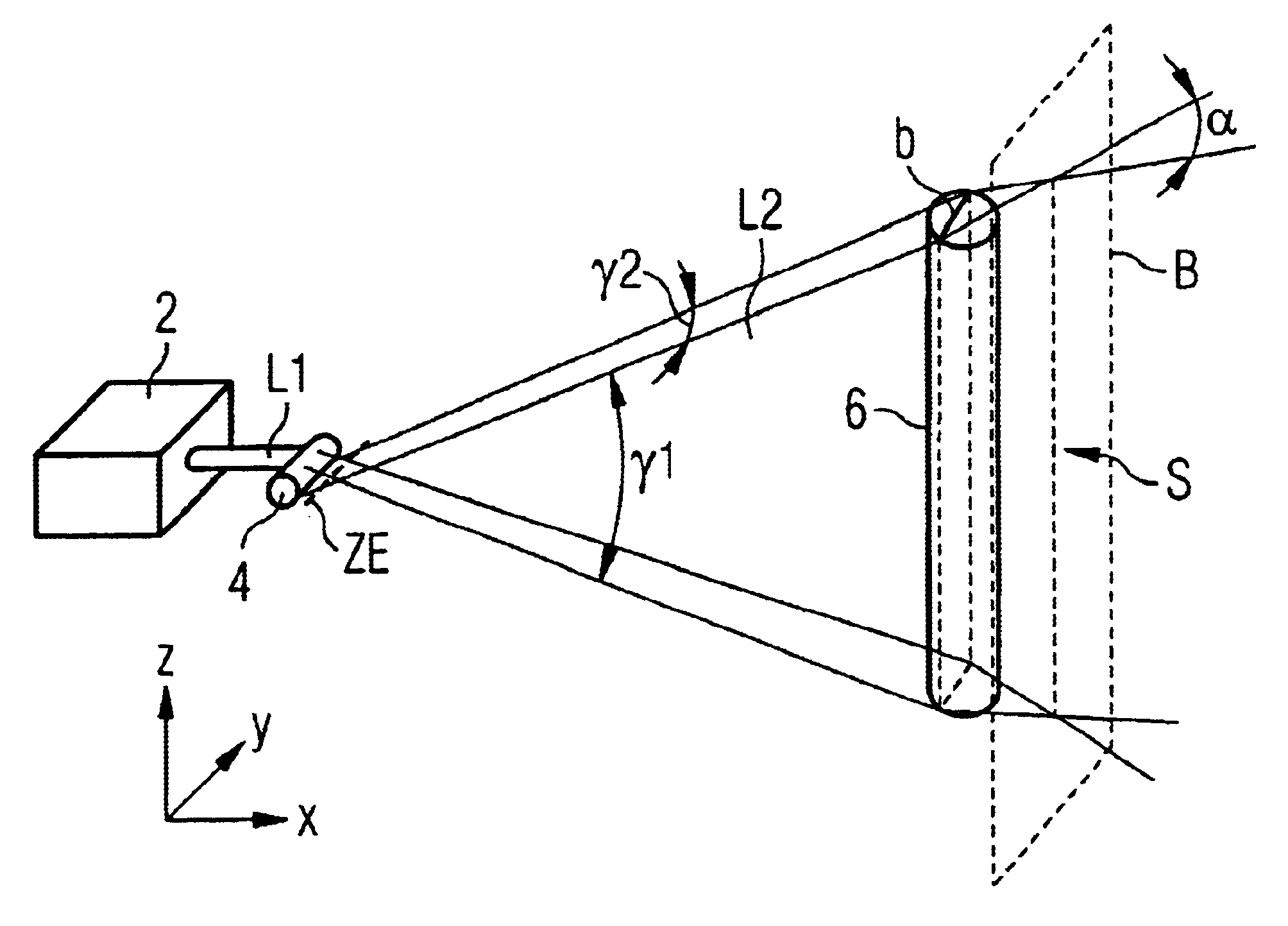
FIG. 1 shows a part of a test apparatus for spectroscopic examination of bank notes, this apparatus serving only as an example of numerous other apparatuses in which the inventive laser illuminating apparatus can be used.

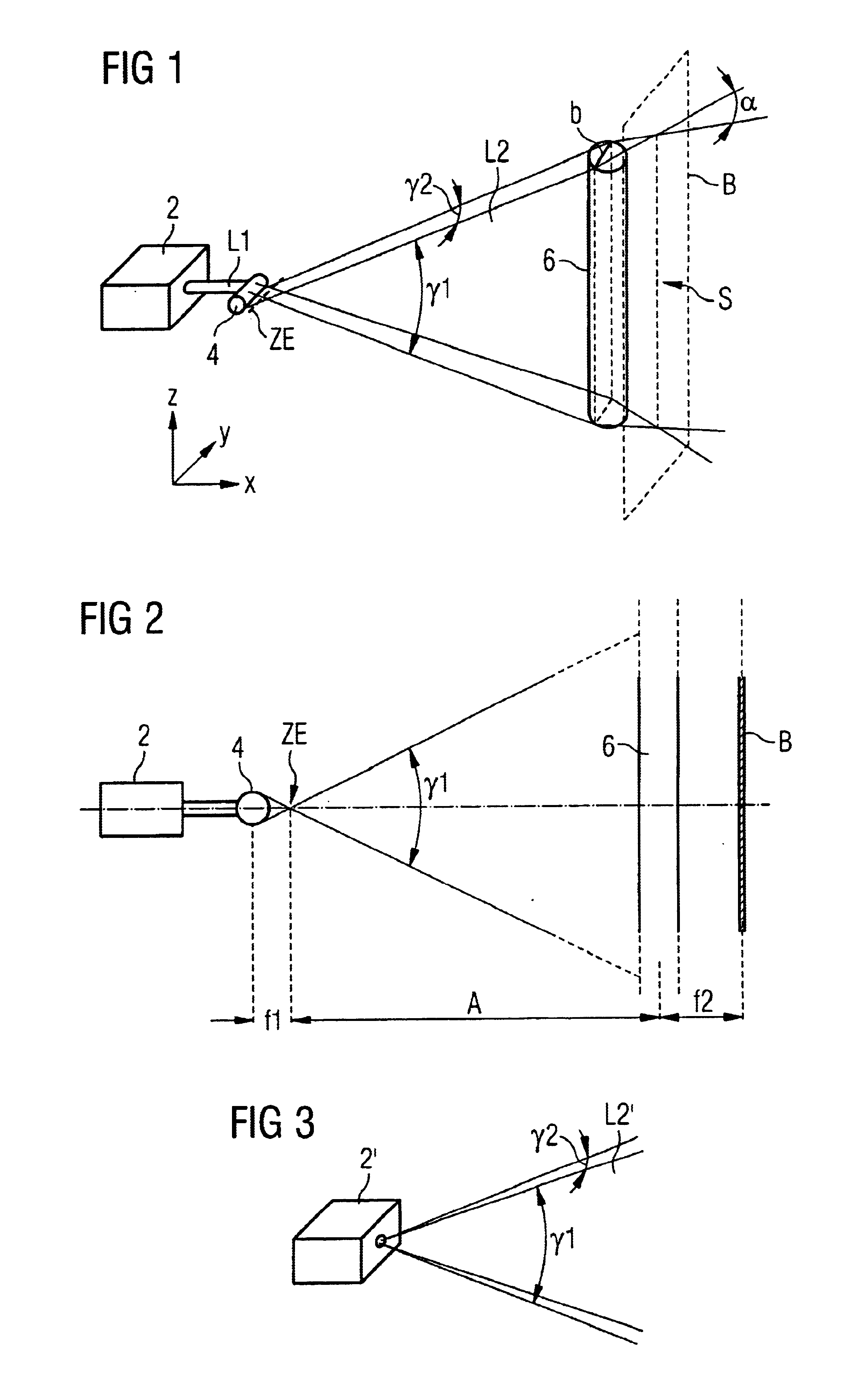
Laser light source 2 formed here for example as a diode laser emits collimated laser beam L1 onto grid rod lens 4 oriented with its longitudinal axis in the Y direction of a Cartesian coordinate system. From collimated laser beam bundle 1 grid rod lens 4 produces laser light beam fan L2 that has its origin in intermediate image plane ZE and is characterized by two divergence angles, namely first divergence angle γ1 in the Z direction and divergence angle γ2 orthogonal thereto in the Y direction.

Laser light beam fan L2 hits rod lens 6 whose longitudinal axis is oriented orthogonally to the longitudinal axis of rod lens 4. As indicated above in FIG. 1, the dimensions of rod lens 6 are coordinated with the cross section of laser light beam fan L2 such that width b of l...


PUM


Abstract

A laser illuminating apparatus that illuminates a linear or strip-shaped area (S) of sheet material (B) with high radiant power contains a diode laser (2) whose output is followed by two mutually orthogonally oriented rod lenses (4, 6) whose focal length is small in comparison to their distance. Between the two rod lenses (4, 6) a laser light beam fan (L2) is formed. Said fan is focused by the second rod lens (6) on a narrow linear area (S). Behind said area the laser beams diverge at a large angle (α) so that the power density decreases accordingly rapidly. If the light falls on the retina of an observer's eye, the laser light is not focused pointwise but only linearly, which excludes injury to the eye due to the accordingly low power density.

Description

BACKGROUND OF THE INVENTIONThis invention relates to a laser illuminating apparatus for illuminating a strip-shaped or linear area of an object, in particular sheet material.Such illuminating apparatuses are used for example in test apparatuses for spectroscopic examination of sheetlike material, for example bank notes, ID cards and the like. Light diffusely reflected or transmitted by the illuminated strip-shaped or linear area of the object is detected by a sensor and evaluated, to detect for example the presence of errors or certain properties.EP 0 762 174 (corresponding to DE 195 32 877) discloses an illuminating apparatus for illuminating a strip-shaped or linear area of sheet material that consists of segments of a cylindrical mirror with an elliptical base. On one of two focal lines there is a light-emitting diode array (LED array), the other focal line corresponds to the illuminated area of the sheet material. Specifically for spectroscopic examination, however, the light em...

Claims


Application Information

Patent Timeline
IPC IPC(8): G02B27/09
CPCG02B27/09
Inventor DECKENBACH, WOLFGANGATTENBERGER, THOMAS
Owner GIESECKE & DEVRIENT GMBH
Why Eureka
Try Eureka