
Substrate-level DC bus design to reduce module inductance

a dc bus and sub-station technology, applied in the field of direct current buses, can solve the problems of increasing energy loss, reducing efficiency, generating heat, and reducing efficiency, so as to reduce inductive power losses, reduce energy loss, and improve motor performance. the effect of uniformity and efficiency

Inactive Publication Date: 2005-01-18
CONTINENTAL AUTOMOTIVE SYST INC
View PDF25 Cites 40 Cited by
  • Summary
  • Abstract
  • Description
  • Claims
  • Application Information

AI Technical Summary

Benefits of technology

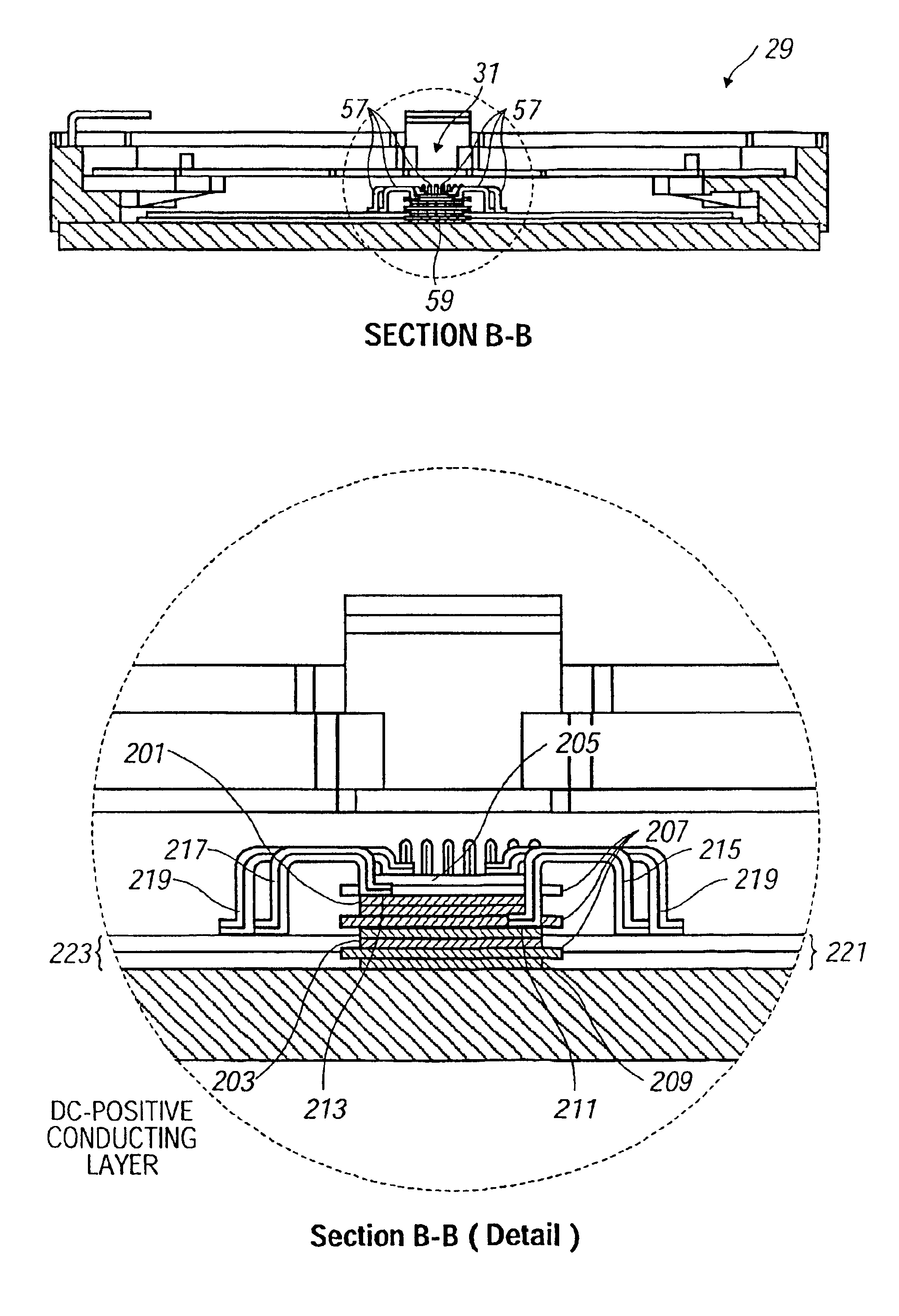
The present invention provides a DC bus for a power module that is shaped and positioned to minimize current loops and reduce inductive power losses. The DC bus allows for symmetrical current flow and counter-flow of electric currents, cancelling magnetic fields and their associated inductances. The DC bus also allows for a more even and efficient motor performance. The invention also includes a lead frame for supporting the module and providing interconnections to the motor and power source, and a substrate with one or more pairs of high and low switches. The invention provides improved efficiency and more even motor performance through the cancellation of magnetic fields and minimization of current loops.

Problems solved by technology

Current flowing through various inductive paths within the module transiently stores energy which increases energy loss, reduces efficiency, and generates heat.
When the flow of current changes, as in such a high frequency switching environment, large voltage overshoots often result, further decreasing efficiency.
In addition, the DC terminals are commonly attached to one end of the power module, which forces current to travel further to some switches for some switching configurations, than for others, resulting in non-uniform current loops.
Current loops that are not uniform result in uneven or inefficient motor performance.

Method used


Image

  • Substrate-level DC bus design to reduce module inductance
  • Substrate-level DC bus design to reduce module inductance
  • Substrate-level DC bus design to reduce module inductance

Examples


Embodiment Construction

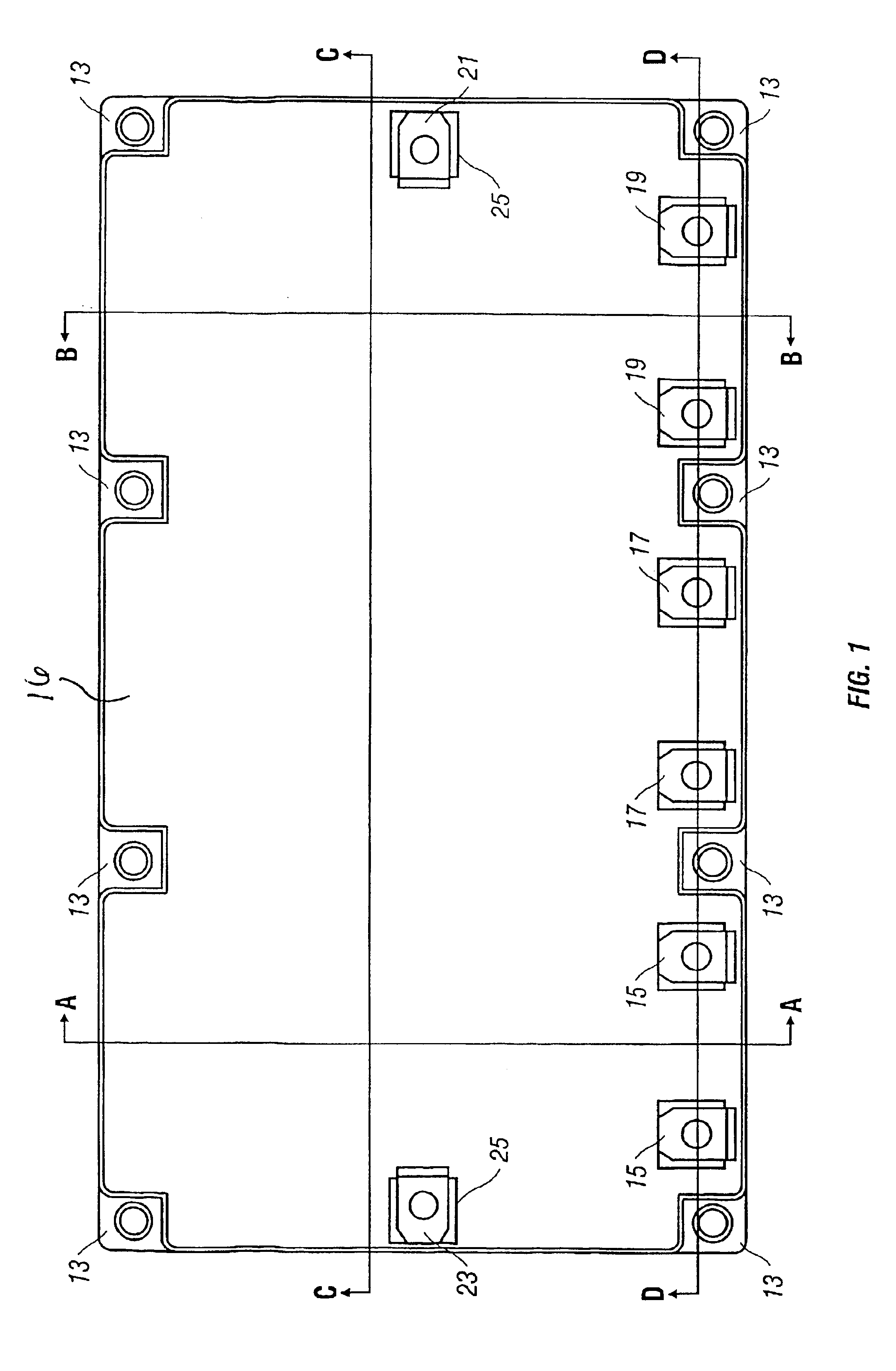
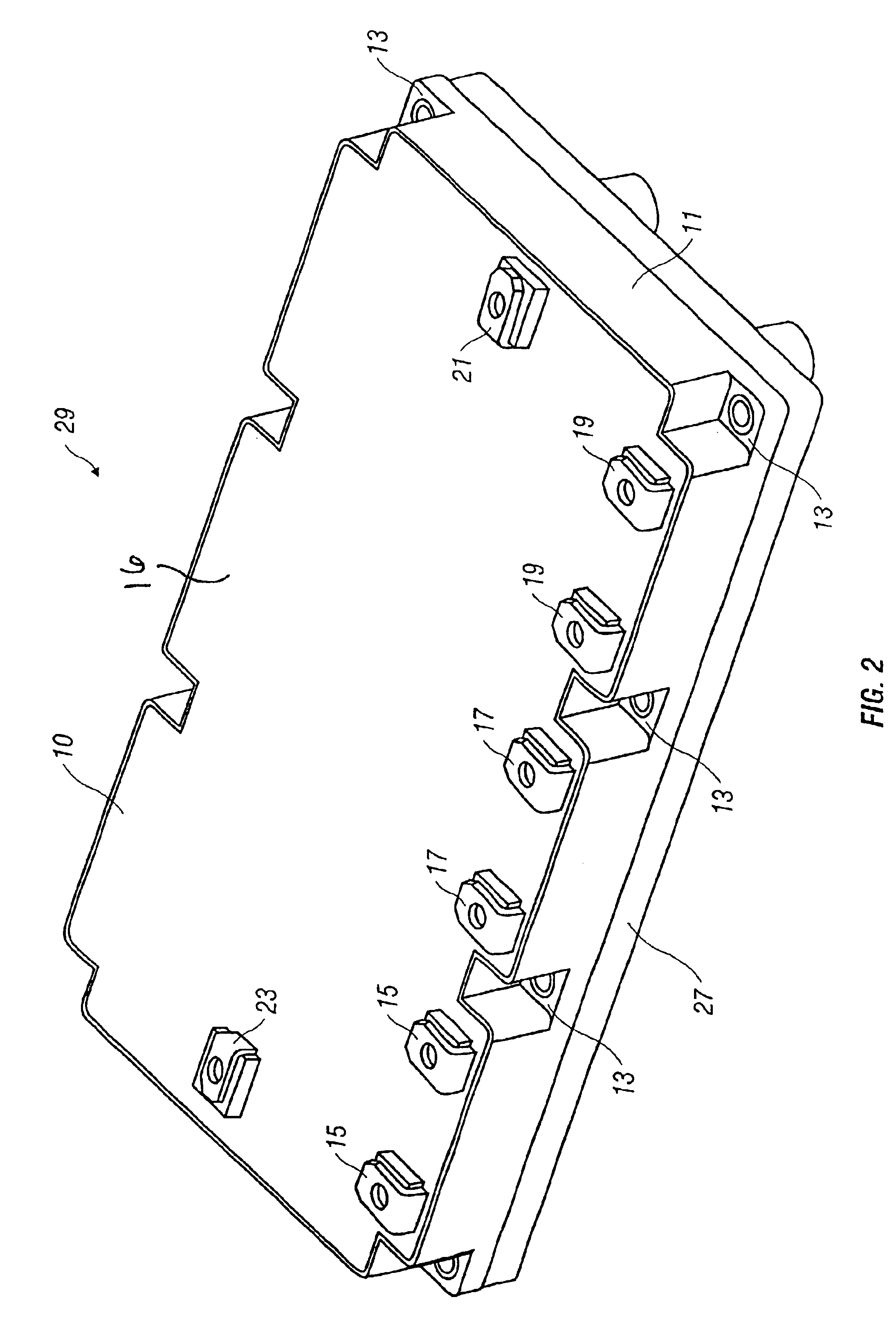
In accordance with the invention, a DC bus is used in a power module, and the DC bus is shaped and positioned to minimize current loops, voltage overshoots and their associated inductance losses, and to provide for symmetric current flow. Reference is made herein to a power module with three phase terminals for use with a three-phase motor and having three bridges, each with two switching pairs. As will be appreciated by one of ordinary skill in the art, the disclosed power module, DC bus, and method for reducing inductance in a power module could be used on a power module with any number of phase terminals and bridges, and having any number of switching pairs. Nonetheless, for ease of description, reference is made to a three-phase power module.

Referring to FIG. 1, an overhead view of the top of the power module is shown. The module has a positive lead 21 that is connectable to a power source, such as a battery, and a negative lead 23 that is likewise connectable to the negative te...


PUM


Abstract

A DC bus for use in a power module includes a positive DC conductor bus plate parallel with a negative DC conductor bus plate. The positive bus and negative bus permit counter-flow of currents, thereby canceling magnetic fields and their associated inductances, and the positive and negative bus are connectable to the center portion of a power module.

Description

BACKGROUND OF THE INVENTION1. Field of the InventionThe invention relates to the field of electronics. More specifically, the invention relates to direct current buses (“DC buses”) used in power modules.2. Background of the InventionAn inverter is commonly used to convert direct current (“DC”) to alternating current (“AC”) to power a three-phase load, such as a three-phase motor, or, alternatively, to convert AC from a three-phase source to DC. The inverter commonly contains six switches. Power modules often contain one or more pairs of complementary switches. The power module typically includes silicon dice on substrates that are secured to the module baseplate. Each switching pair has a positive or “high” side switch and a negative or “low” side switch for controlling the flow of electric current. Each switching pair is referred to herein as a “half bridge.” The “high side” of the bridge contains the positive switches, and the “low side” contains the negative switches. By the term...

Claims


Application Information

Patent Timeline
Patent Type & Authority Patents(United States)
IPC IPC(8): H01L23/58H01L23/66H01L25/07H05K1/02H05K1/03
CPCH01L23/50H01L23/66H01L25/072H01L2924/1305H01L2924/13055H01L2924/13091H01L2924/30107H01L2224/49175H01L2224/48472H05K2203/049H01L2223/665H01L2924/3011H05K1/0215H05K1/0237H05K1/0306H05K2201/09345H05K2201/10446H05K2201/10636H01L2924/00Y02P70/50H01L2924/19107
Inventor AHMED, SAYEEDPARKHILL, SCOTTFLETT, FREDMALY, DOUGLAS
Owner CONTINENTAL AUTOMOTIVE SYST INC
Learn More