Shaft seals for sealing pulverulent solids

a technology of shaft seals and solids, which is applied in the direction of engine seals, ball bearings, bearings, etc., can solve the problems of failure of seals, leakage of fluid medium in which the seal is working, and inapplicability to applications

Inactive Publication Date: 2005-01-18
BAYNE CHRISTOPHER FREDERICK
View PDF14 Cites 38 Cited by
  • Summary
  • Abstract
  • Description
  • Claims
  • Application Information

AI Technical Summary

Benefits of technology

Providing that the passage is tortuous also helps to achieve...

Problems solved by technology

Any leakage of the fluid medium in which the seal is working which takes place past the seal is most likely to occur at the interface.
Also, a primary cause of failure of a seal is due to abrasive matter which is entrained in the fluid medium which penetrates between the stator and the rotor at the interface or the build up of heat due to rubbing contact between the stator and the rotor at the interface.
For this reason, and also due to...

Method used


Image

  • Shaft seals for sealing pulverulent solids
  • Shaft seals for sealing pulverulent solids
  • Shaft seals for sealing pulverulent solids

Examples


Embodiment Construction

For the sake of avoiding repetition, in this specification the use of the phrase “in the present example” or words to the same effect is intended to indicate that what is being described is by way of illustrative example and that there is no intention that the scope of the invention be limited thereto unless this appears from the context. On the other hand, there is no intention that in the absence of a phrase of the same kind, the scope of the invention is to be limited by any matter described unless this appears from the context.

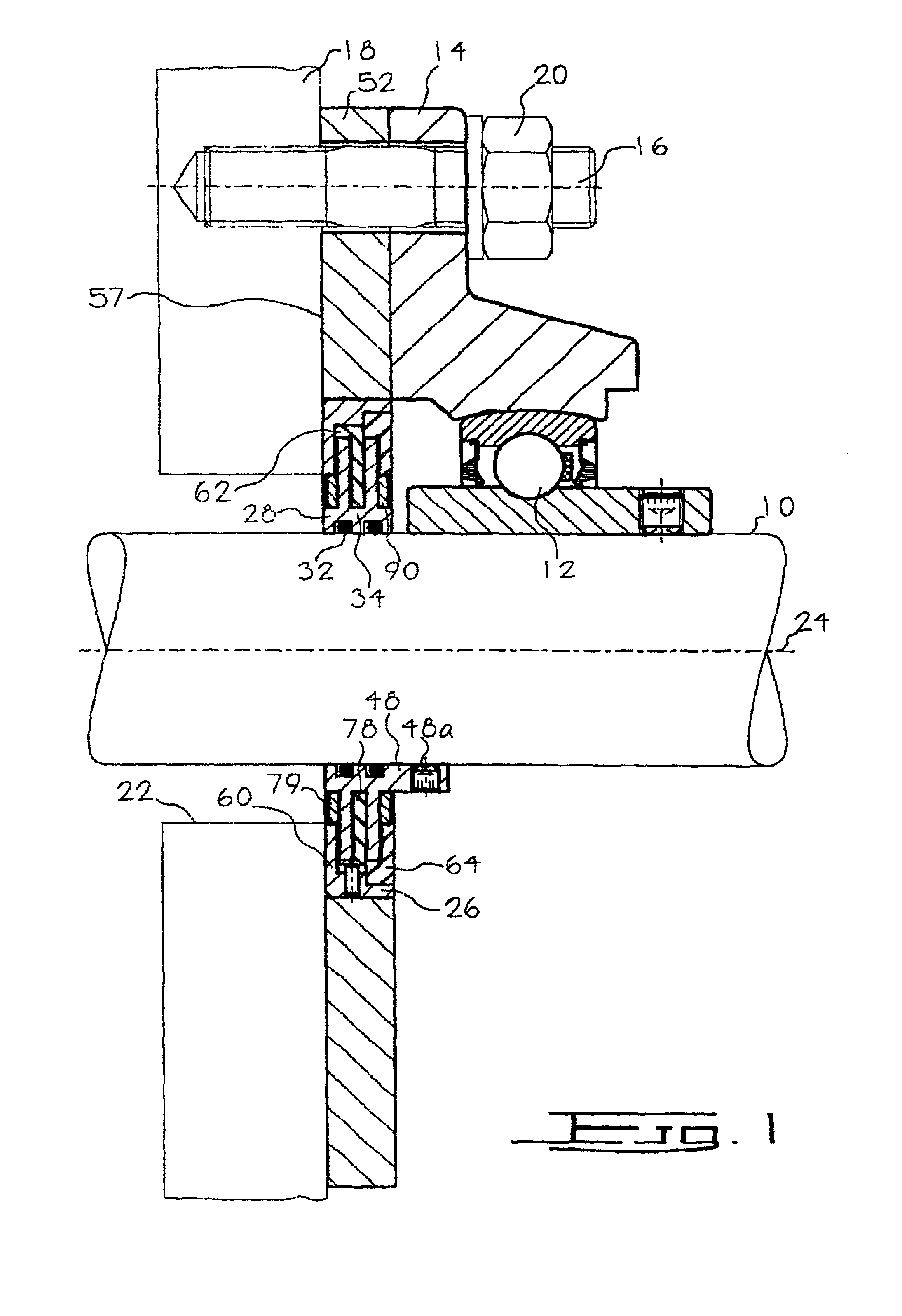
Referring first to FIGS. 1 to 3, there is shown a shaft 10 carried in a ball bearing assembly 12 seated in a housing 14. The ball bearing assembly 12 and the housing 14 can be a commercially available “off the shelf” unit and need not be described in detail. The housing 14 is mounted over four threaded machine bolts or studs 16 fixed on a plate 18 and held in place by means of nuts and washers 20.

In the present case the plate 18 is the vertically disposed ...


PUM


Abstract

An apparatus and method for providing a seal between first and second relatively rotatable parts of machines which operate in an environment comprising dust, grit or other finely divided solid material entrained in air, water or other fluid. The seal includes a rotor and a stator between which there is an annular passage with substantial clearance between the interfacing surfaces defining the passage. The solid material entrained in the fluid which enters the annular passage is deposited in layers on the interfacing surfaces when the mechanism is in use. The layers substantially reduced the cross sectional size of the annular passage and restrict flow of the fluid there through. The annular passage may be rendered tortuous by providing the rotor with annular fins which in use project into annular recesses in the stator, and vice versa.

Description

FIELD OF THE INVENTIONThere are countless applications in industry in which a mechanism is called for which comprises a rotatable member (such as a shaft) which passes through or is seated or supported in or adjacent an aperture in some stationary part of the mechanism (such as a wall or bearing housing).BACKGROUND OF THE INVENTIONThe present invention is particularly but not necessarily exclusively concerned with equipment in which such mechanisms operate in an environment in which finely divided solids are present, the solids being carried either in a fluid such as air (or other gas) or water (or other liquid). Such equipment includes screw conveyors, bucket elevators, ribbon mixers, so-called Z mixers, rotary valves, augers, pulverizers, hammer mills, powder transfer equipment and other mixing equipment. This list is not intended to be exhaustive and the invention could in principle be applied to any suitable equipment which operates in conditions in which it is desirable that ga...

Claims


Application Information

Patent Timeline
IPC IPC(8): F16J15/00F16J15/447F16J15/44
CPCF16J15/002F16J15/3472F16J15/4472F16C33/80F16C35/045F16J15/4474F16C23/084F16C19/06
Inventor BAYNE, CHRISTOPHER FREDERICK
Owner BAYNE CHRISTOPHER FREDERICK
Why Eureka
Try Eureka