
Polarization independent broad wavelength band optical switches/modulators

a technology of broad wavelength band and optical switch, applied in the field of polarization independent broadband optical switch and switch, can solve the problems of optical switch defective, difficult to achieve precise length of 3 db coupler, and limited fabrication tolerances

Inactive Publication Date: 2005-01-11
EOSPACE
View PDF5 Cites 23 Cited by
  • Summary
  • Abstract
  • Description
  • Claims
  • Application Information

AI Technical Summary

Benefits of technology

[0014]An object of the invention is to solve at least the above problems and/

Problems solved by technology

Ldc precision is limited by fabrication tolerances, and a precise length for the 3 dB couplers is hard to achieve.
For example, a 10% variation in coupler length can render an optical switch defective.
Thus, a low crosstalk (<−25dB) switch is difficult to achieve.
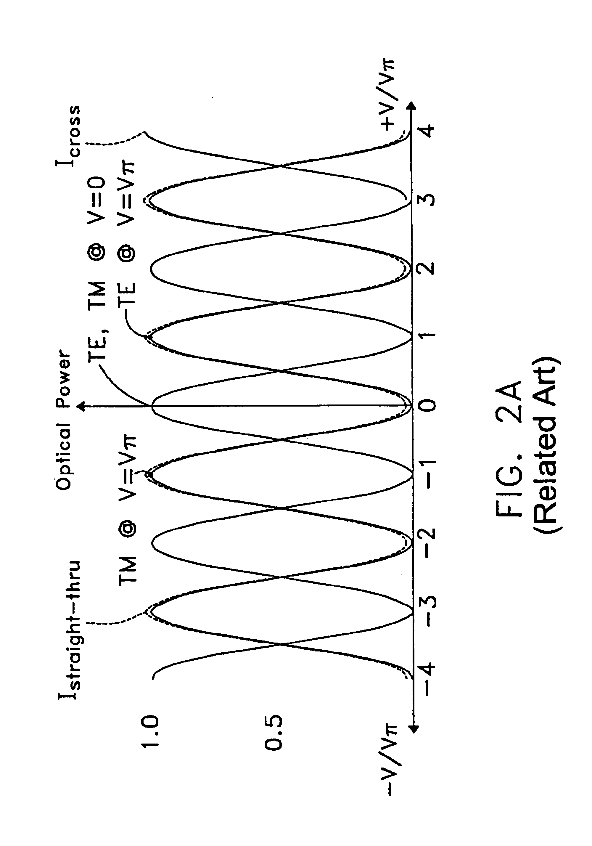
Thus, it is difficult to achieve an exact 3 dB coupling for both TE and TM modes simultaneously.
This will result in an undesirable high crosstalk for either TE or TM modes or both.

Method used


Image

  • Polarization independent broad wavelength band optical switches/modulators
  • Polarization independent broad wavelength band optical switches/modulators
  • Polarization independent broad wavelength band optical switches/modulators

Examples


Embodiment Construction

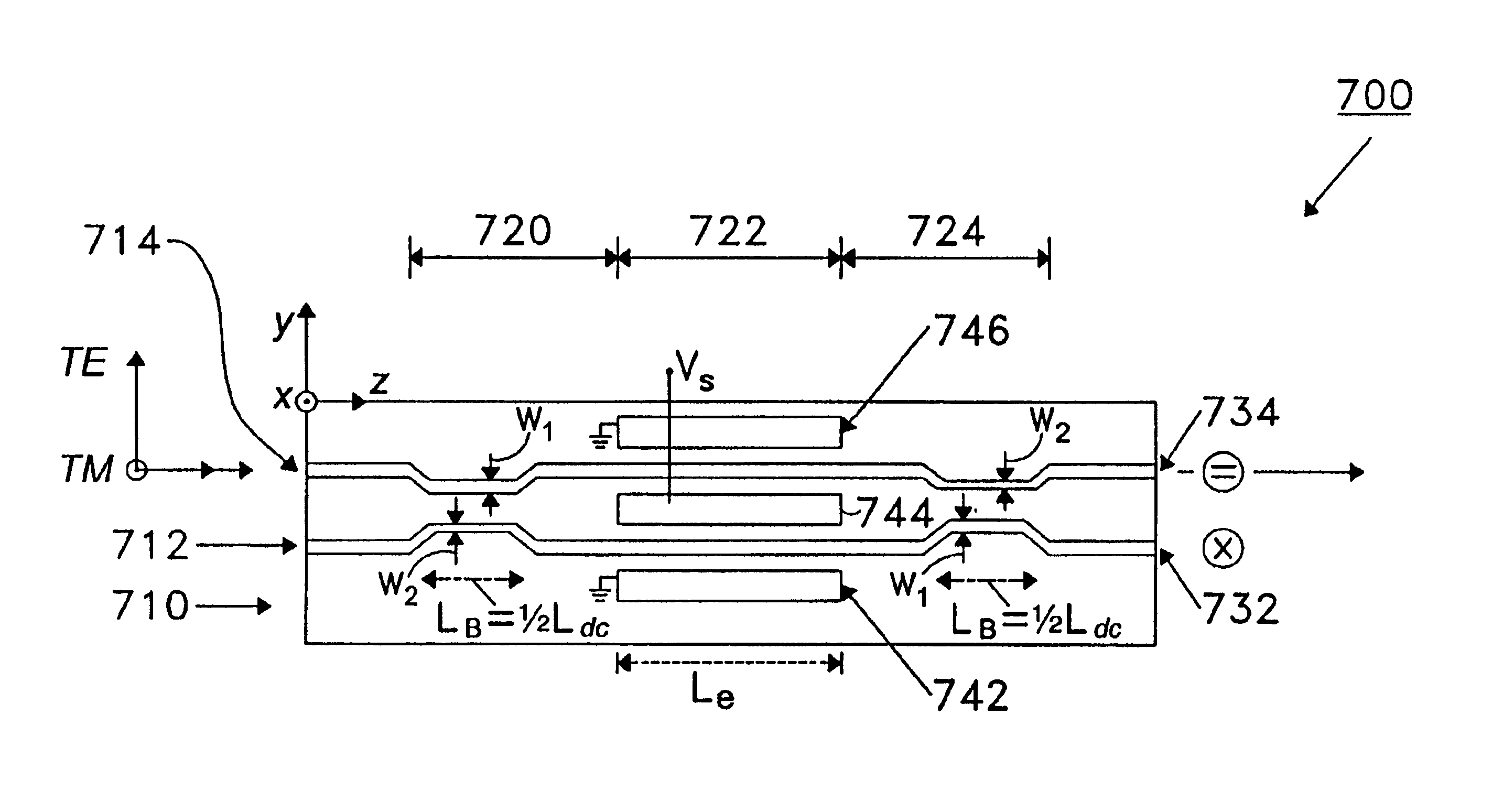
[0049]FIG. 3A is a diagram that illustrates a first preferred embodiment of a broad wavelength band polarization independent optical switch, in accordance with the present invention. “Broad wavelength band” includes the range of wavelengths from at least approximately 1530 nm (nanometer) to at least approximately 1610 nm. The switch's functioning wavelength range includes the C and L bands, where the C band spans approximately 1530 nm to 1565 nm, and the L band spans approximately 1565 nm to 1610 nm. However, the switch's functioning is not limited to the wavelength range encompassing the L and C band, and the switch will function substantially below and substantially above both those bands, inclusively. “Polarization independent” means that the switch may effectively switch any polarization or all components of an optical signal. The first preferred embodiment of the optical switch is a polarization-independent, broad-wavelength band 2×2 switch using a balanced-bridge interferomete...


PUM


Abstract

Optical switches based on the balanced bridge interferometer design require precisely made (or half a coupling length) directional couplers to achieve minimum crosstalk for the two switch outputs. Precision 3 dB-directional couplers require the waveguide dimensions and fabrication parameters of the evanescent region to be tightly controlled making a low crosstalk switch difficult to manufacture and expensive. A new type of balanced bridge interferometer type switch is disclosed where the input and output directional couplers are asymmetrically biased to induce a certain difference in the propagation constants between the two waveguide in the directional couplers. By using the asymmetrically biased directional couplers with a certain tuning a bias voltage for the directional couplers. Low crosstalk switches can be achieved for a very wide range of directional coupler strengths, relaxing the precise half-coupling length directional couplers required in conventional design. This relaxation of the precise directional coupler waveguide regions allows a relaxation in the manufacturing tolerance of the devices and therefore make the switch much easier to make. Because low crosstalk switches can be a device with an extended operating range and broader directional coupler parameters, switches can be used for a much broader wavelength bandwidth. In one of the embodiments, this new design allows a device to switch both TE and TM mode optical signals simultaneously at low crosstalk levels to result in a polarization-independent optical switch.

Description

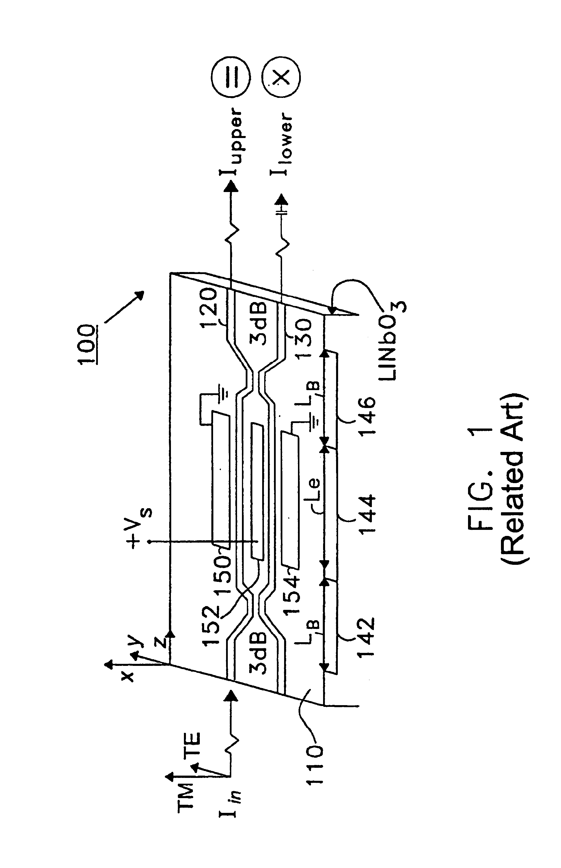
[0002]This application claims priority to U.S. Provisional Application Ser. Nos. 60 / 204,774 and 60 / 204,775, both filed May 17, 2000, whose entire disclosure is incorporated herein by reference.BACKGROUND OF THE INVENTION[0003]1. Field of the Invention[0004]The present invention relates to electro-optic devices, and in particular, to polarization independent broadband optical modulators and switches for wideband fiberoptic networks.[0005]2. Background of the Related Art[0006]A balanced bridge optical switch has two input and two output waveguides. Two ½lc (half a coupling length) 3-dB (i.e., 50:50 power splitter) directional couplers and a phase modulated interferometer waveguide pair are used. Note that “lc” is the characteristic coupling length of a directional coupler, which is the length of the directional coupler necessary to transfer substantially all the power from a first waveguide to a second waveguide. The input 3-dB coupler is used to equally divide an input signal receive...

Claims


Application Information

Patent Timeline
IPC IPC(8): G02F1/29G02F1/313
CPCG02F1/3136G02F2203/06
Inventor THANIYAVARN, SUWAT
Owner EOSPACE
Learn More