
Electrochromic windows and method of making the same

Inactive Publication Date: 2005-01-11
GENTEX CORP
View PDF33 Cites 211 Cited by
  • Summary
  • Abstract
  • Description
  • Claims
  • Application Information

AI Technical Summary

Benefits of technology

Accordingly, an aspect of the present invention is to provide an improved electrochromic window construction. More specifically, an aspect of the invention is to provide an electrochromic window that is easier to mass-produce and that utilizes less expensive components and lower quantities of the costlier components. Another aspect of the present invention is to provide an electrochromic window that exhibits markedly improved color stability. Still another aspect of the present invention is to provide an electrochromic window having improved thermal deflection / emission characteristics. Yet another aspect of the invention is to provide an electrochromic window having an improved seal construction.

Problems solved by technology

Electrochromic windows have not been widely accepted commercially for several reasons.
First, they tend to be very expensive due to the cost of materials required for their construction, and their complex construction makes mass production difficult.
Additionally, electrochromic windows have tended to have a lower life expectancy than conventional windows due to degradation of the electrochromic materials used in the window.
The combination of added cost and lower life expectancy have deterred many architects and builders from using electrochromic windows.

Method used


Image

  • Electrochromic windows and method of making the same
  • Electrochromic windows and method of making the same
  • Electrochromic windows and method of making the same

Examples


example 1

Two of the above constructed windows were filled with a solution containing 16 mM dimethyl-4,4′-bipyridinium bis(tetrafluoroborate); 16 mM 5,10-dihydro-5,10-dimethyl phenazine and 30 mM 4′-methyl-2′-hydroxy-phenyl-benzotriazole (Tinuvin P) in propylene carbonate (PC) with 3 wt % polymethyl methacrylate (PMMA). The color coordinates (L*a*b* D65 / 2°) of transmitted light were recorded and the windows were then subjected to 730 hours of high intensity UV light in an Atlas Weather-Ometer with an Xe lamp operating at 0.55 W / m2 at 340 nm (a darkening cycle consisting of operation of the device at 1.2V for 20 sec. and at 0.0V for 40 sec., these times allowed for the devices to undergo darkening to their steady state transmission values and allow the devices to clear completely). The color coordinates were again recorded and the difference (ΔE) for the windows in their high transmission condition was 2.50 and 2.22 for the low transmission condition ΔE was 4.45 and 4.99.

example 2

Two windows were constructed the same as in Example 1, but were filled with 16 mM bis(2-phenyl ethyl)-4,4′-bipyridinium bis(tetrafloroborate) 16 mM DMP, 30 mM Tinuvin P in PC with 3 wt % PMMA. A similar test as performed to Example 1 was performed except that the windows were measured after 629 hours. These windows exhibited a ΔE (high transmission) of 1.18 and 1.121 and a ΔE (low transmission) of 1.09 and 1.33.

example 3

Two windows were constructed having the same structure as in Examples 1 and 2 above except that the windows were filled with 15 mM bis(3-phenyl propyl)-4,4′-bipyridinium bis(tetrafluoroborate), 16 mM DMP 30 mM Tinuvin P in PC with 3 wt % PMMA after 629 hours, which is a conventional electrochromic material. Accordingly, this example served as a control for purposes of comparison with Examples 1 and 2 above. The following measurements were made after 629 hours in the Weather-Ometer. Specifically, the conventional window exhibited a ΔE (high transmission) of 6.72 and 9.93 and a ΔE (low transmission) of 7.50 and 10.01.


PUM


Abstract

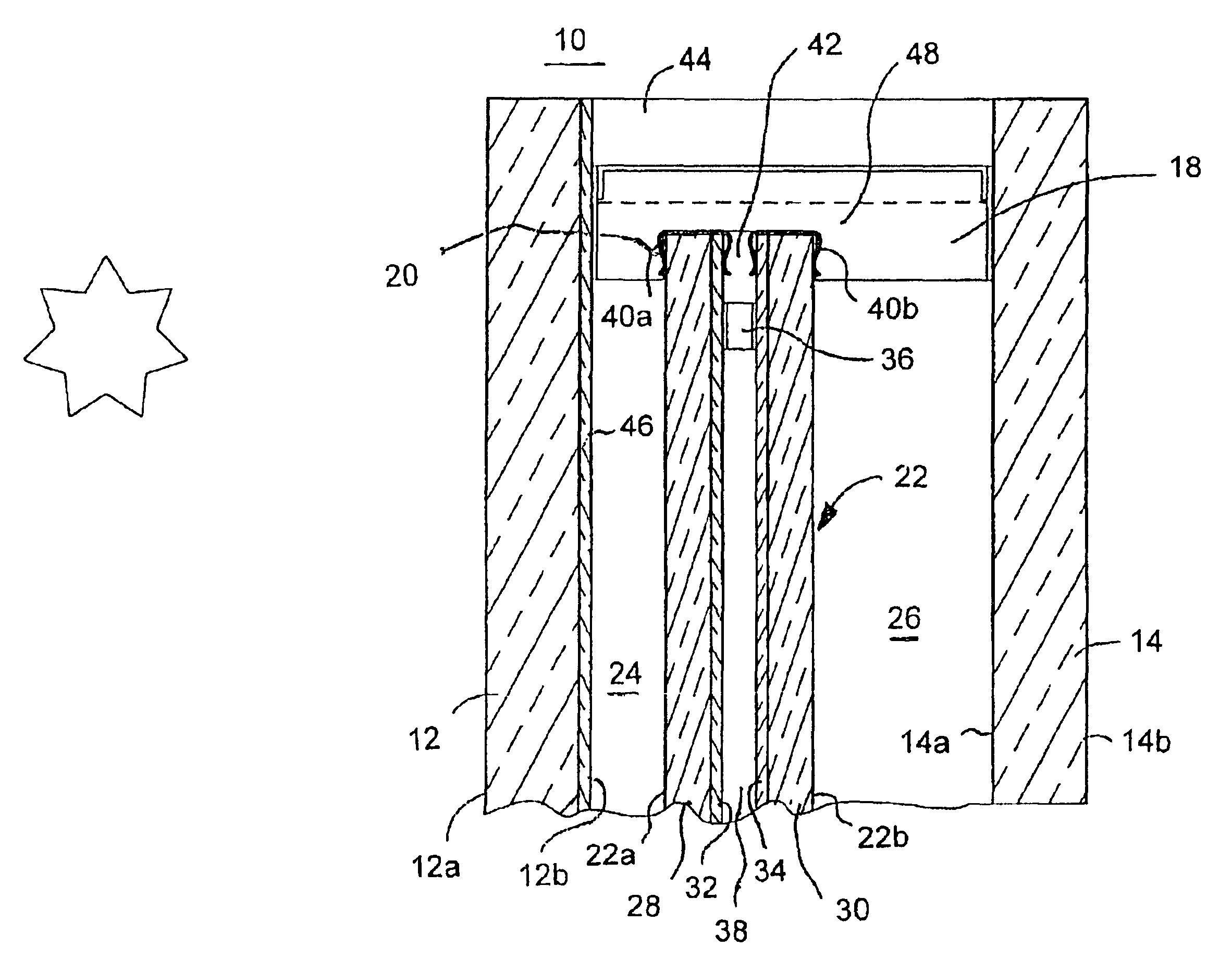
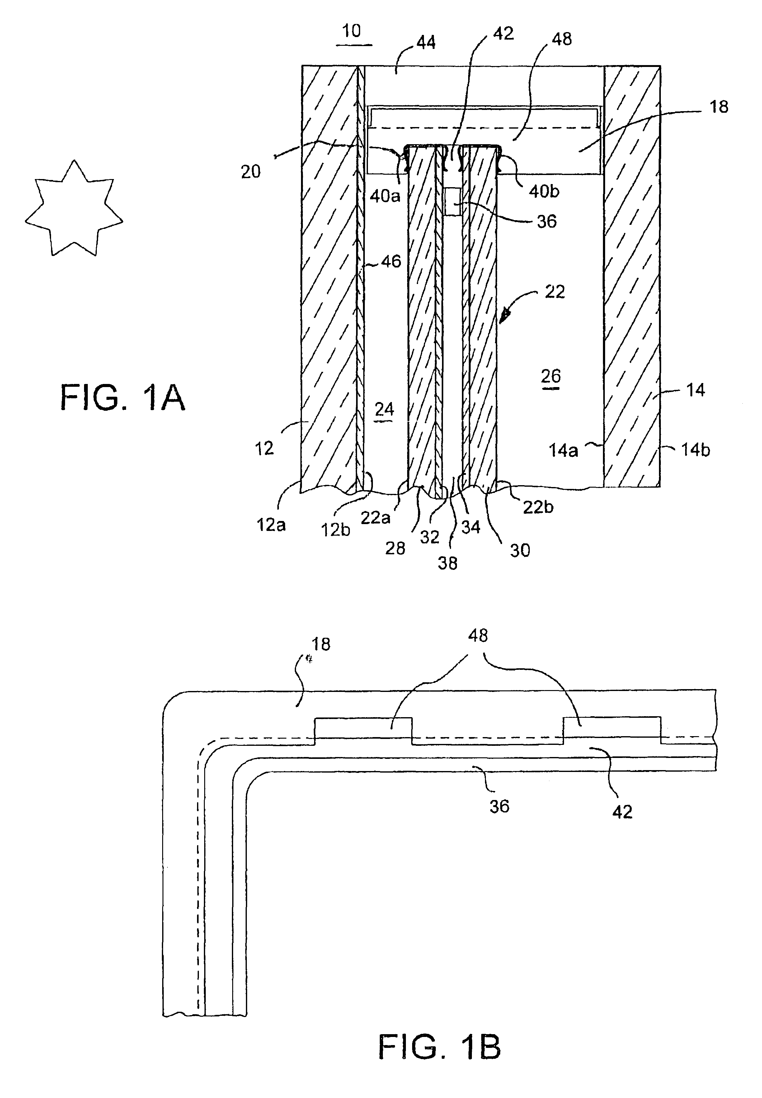
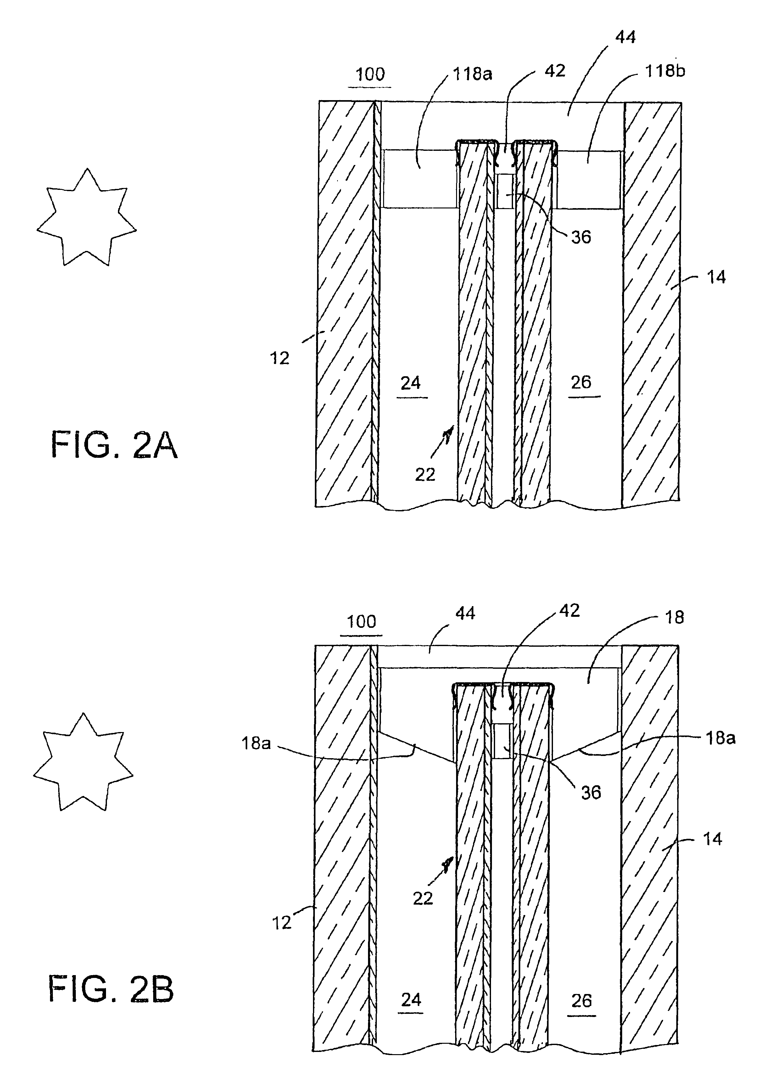
An electrochromic window assembly is disclosed that includes a first substrate and a second substrate that is maintained in a parallel and spaced relation from the first substrate by means of a window frame and spacer. The window assembly further includes an electrochromic device mounted within the airtight chamber formed between the first and second substrates. Electrochromic device 22 may be mounted so as to provide an air chamber between first substrate 12, which is the external substrate, and electrochromic device 22. At least one of the chambers formed between substrates 12 and 14 and electrochromic device 22 may be filled with an insulating gas such as argon. Also disclosed are novel methods for manufacture of an electrochromic device for incorporation into such a window assembly. A novel electrochromic device is also disclosed having electrical bus clips secured about the entire periphery of the electrochromic device. Also disclosed is the use of steel bus clips for the electrochromic device.

Description

BACKGROUND OF THE INVENTIONThe present invention generally relates to windows having variable transmittance light filters, and more specifically to windows including electrochromic light filters.Variable transmittance light filters, such as electrochromic light filters, have been proposed for use in architectural windows, skylights, and in windows and sunroofs for automobiles. Such electrochromic light filters reduce the transmittance of direct or reflected sunlight during daytime through the window, while not reducing such transmittance during nighttime. Not only do such light filters reduce bothersome glare and ambient brightness, but they also reduce fading of interior materials and heat load caused by the transmittance of sunlight through the window.Electrochromic windows have not been widely accepted commercially for several reasons. First, they tend to be very expensive due to the cost of materials required for their construction, and their complex construction makes mass prod...

Claims


Application Information

Patent Timeline
IPC IPC(8): E06B3/66E06B3/663G02F1/01G02F1/153E06B3/67G02F1/155G02F1/161E06B9/264G02F1/15
CPCE06B3/66E06B3/66366E06B3/6775E06B9/264G02F1/153G02F1/1533G02F1/161E06B3/6722G02F2201/44G02F1/155E06B2009/2464Y10S359/90
Inventor POLL, DAVID L.ASH, KEVIN L.THEISTE, DAVID A.GUARR, THOMAS F.TONAR, WILLIAM L.
Owner GENTEX CORP
Learn More