
Ramp generator

a technology of ramp generator and ramp generator, which is applied in the direction of digital-analog converters, transmission systems, instruments, etc., can solve the problems of ramp generators that ramp generators can pose significant physical size problems, and methods used have not enabled a reduction in the size of the overall ramp generator, so as to avoid or mitigate the

Inactive Publication Date: 2005-01-11
STMICROELECTRONICS (RES & DEV) LTD
View PDF7 Cites 5 Cited by
  • Summary
  • Abstract
  • Description
  • Claims
  • Application Information

AI Technical Summary

Benefits of technology

An object of the present invention is to provide a ramp generator that is suitable for inclusion in an ADC in an image sensor, and one that avoids or mitigates the above described problems.

Problems solved by technology

Known ramp generators using ADCs, switched capacitor integrators, charge pumps or the use of current into a capacitor suffer from a number of problems, such as the following: offsets, achieving the necessary gain within the time constants required for settling, area and power inefficiency, non-monotonicity, and process / temperature dependence.
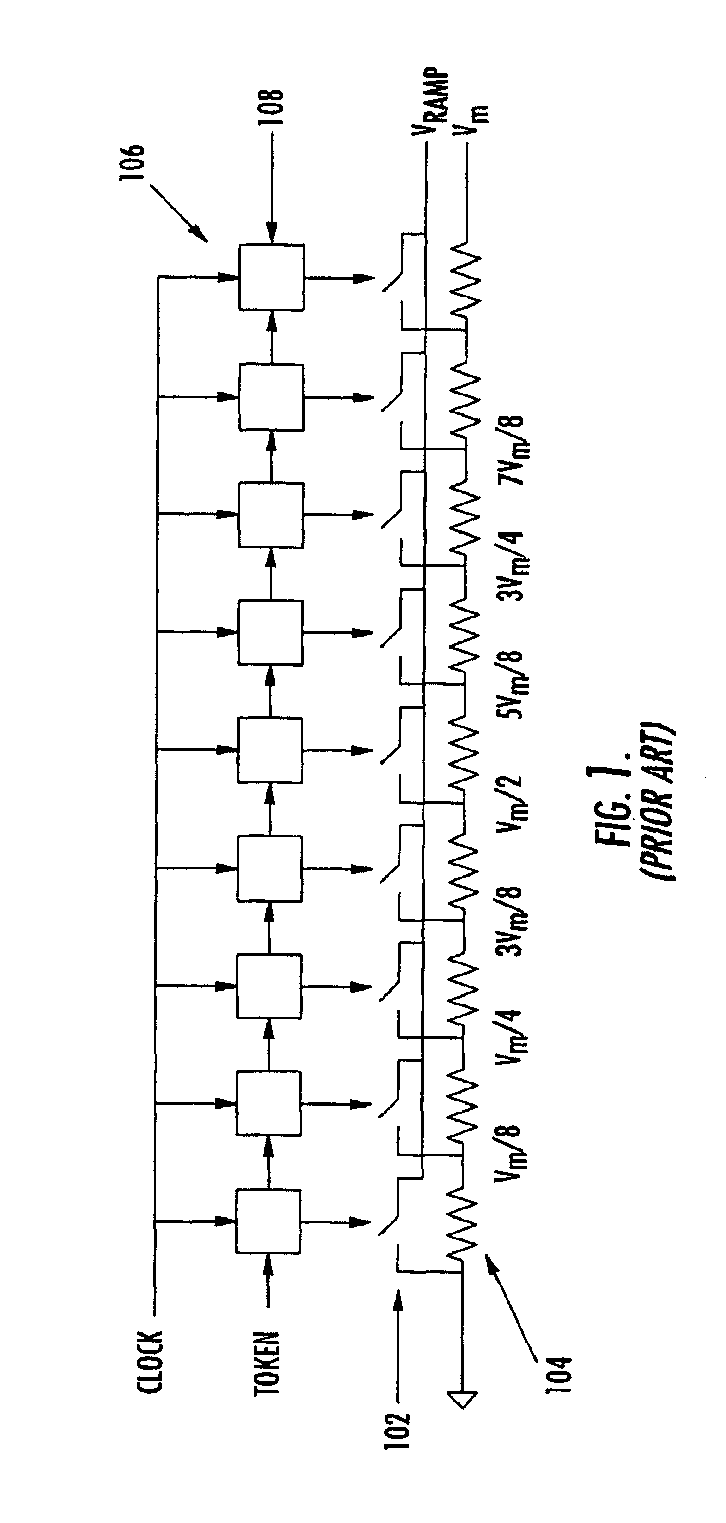
This type of ramp generator can pose a significant problem in terms of physical size since a 12 bit ramp generator requires 2048 shift register elements and 2048 resistive elements.
This can be prohibitive when IC space is at a premium and the quality of ramp generation is paramount.
The methods used have not enabled a reduction in size of the overall ramp generator, but in fact have increased the overall size by using a digital control circuit to control the closing of the switches.
This had advantages in other areas but significantly increases the complexity and the physical size of the ramp generator when integrated on an integrated circuit.

Method used


Image

  • Ramp generator
  • Ramp generator
  • Ramp generator

Examples


Embodiment Construction

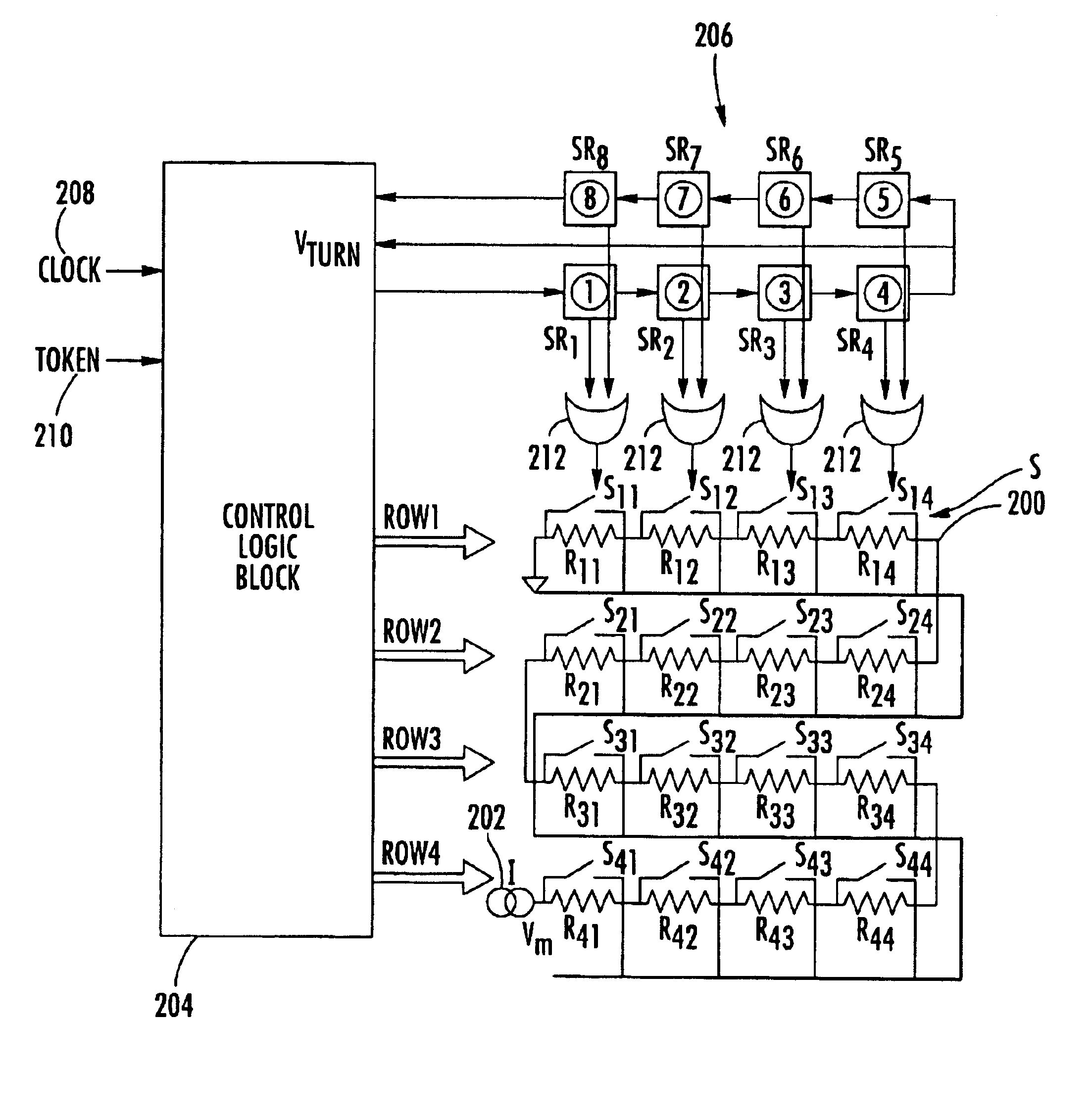
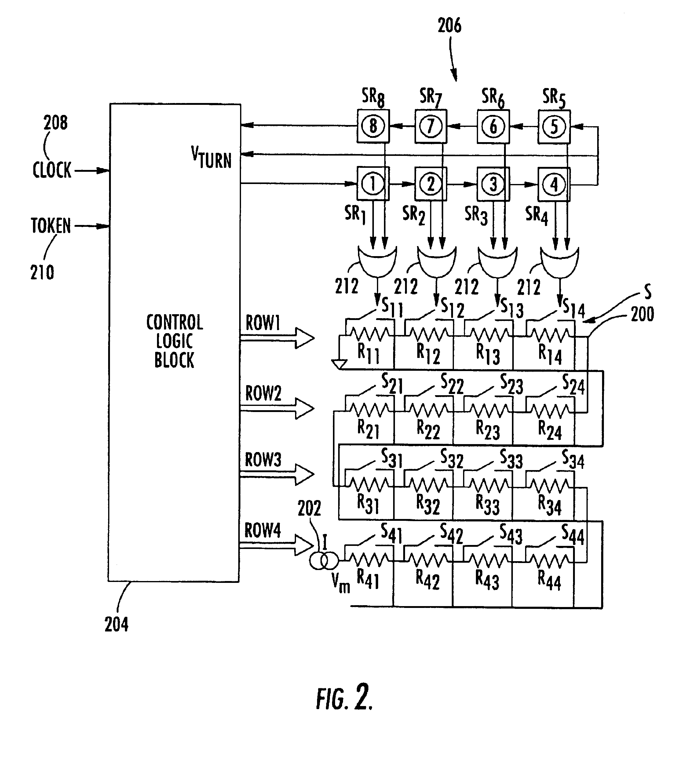
Referring to FIG. 2, a resistance ladder 200 is formed by a series of resistors R11 . . . R44. The resistance ladder 200 is supplied with a constant current I by a constant current source 202. An output VRamp can be tapped from each point along the resistance ladder 200 by the operation of switches S11-S44.

By operating the switches S11-S44 sequentially, with only one switch being closed at a time, a stepped ramp voltage will be obtained at VRAMP. If all the resistors R have the same value RUNIT, then

VRAMP=N*RUNIT*I

where N is the number of resistors in series when the respective switch is closed.

The switches S11-S44 are operated by a combination of a control logic block 204 and a shift register 206. The control logic block 204 accepts a clock input 208 and a token input 210. The clock input 208 is a regular clock pulse signal at a pre-determined frequency which ultimately governs the length of time a single voltage ramp takes to rise.

The token input 210 is a single high pulse which i...


PUM


Abstract

A ramp generator includes a resistance ladder (10) supplied with a constant current. Switches are closed in sequence on the resistance ladder to generate the ramp voltage. By using control logic to decode the sequence, a looped shift register is used to close the switches.

Description

FIELD OF THE INVENTIONThe present invention relates to a ramp generator that can be used in an analog-to-digital converter (ADC), and to an ADC including a ramp generator. A field of application for the present invention is in solid-state image converters.BACKGROUND OF THE INVENTIONIn CMOS image sensors an ADC arrangement is used wherein a voltage of each pixel is compared with a ramp voltage. At the point where the ramp voltage equals the pixel voltage, a comparator latches a digital count value into a memory. In this architecture, the resolution of the ADC is directly related to the resolution and linearity of the ramp generation circuitry.Known ramp generators using ADCs, switched capacitor integrators, charge pumps or the use of current into a capacitor suffer from a number of problems, such as the following: offsets, achieving the necessary gain within the time constants required for settling, area and power inefficiency, non-monotonicity, and process / temperature dependence.Shi...

Claims


Application Information

Patent Timeline
Patent Type & Authority Patents(United States)
IPC IPC(8): H03K4/02H03K4/00G06J1/00
CPCH03K4/026G06J1/00
Inventor LAFLAQUIERE, ARNAUD
Owner STMICROELECTRONICS (RES & DEV) LTD
Learn More