
Method for actively decreasing the temperature of a heatable soleplate in a textile treatment device

a technology of textile treatment device and temperature reduction, which is applied in the field of garment care, can solve problems such as textiles (of garments) getting damaged

Active Publication Date: 2021-06-08
VERSUNI HLDG BV
View PDF28 Cites 0 Cited by
  • Summary
  • Abstract
  • Description
  • Claims
  • Application Information

AI Technical Summary

Benefits of technology

The technical effect of this patent is to provide a better method and device for treating textiles that solves or reduces the problems mentioned earlier.

Problems solved by technology

In case the ironing device is no more in movement with respect to the textile (of the garments) being ironed, which could for example be caused by the user being suddenly called on the phone, there is a risk that the textile (of the garments) will get damaged due to a prolonged time duration of no movement of the ironing device on the textile (of the garments).

Method used


Image

  • Method for actively decreasing the temperature of a heatable soleplate in a textile treatment device
  • Method for actively decreasing the temperature of a heatable soleplate in a textile treatment device
  • Method for actively decreasing the temperature of a heatable soleplate in a textile treatment device

Examples


first embodiment

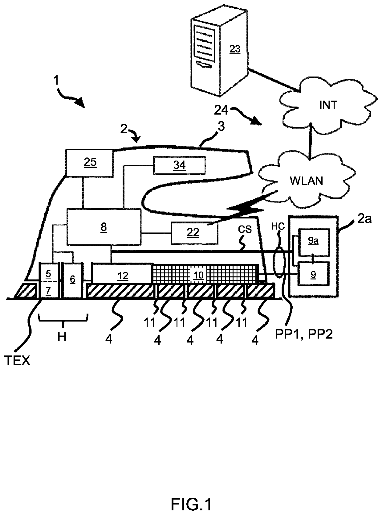
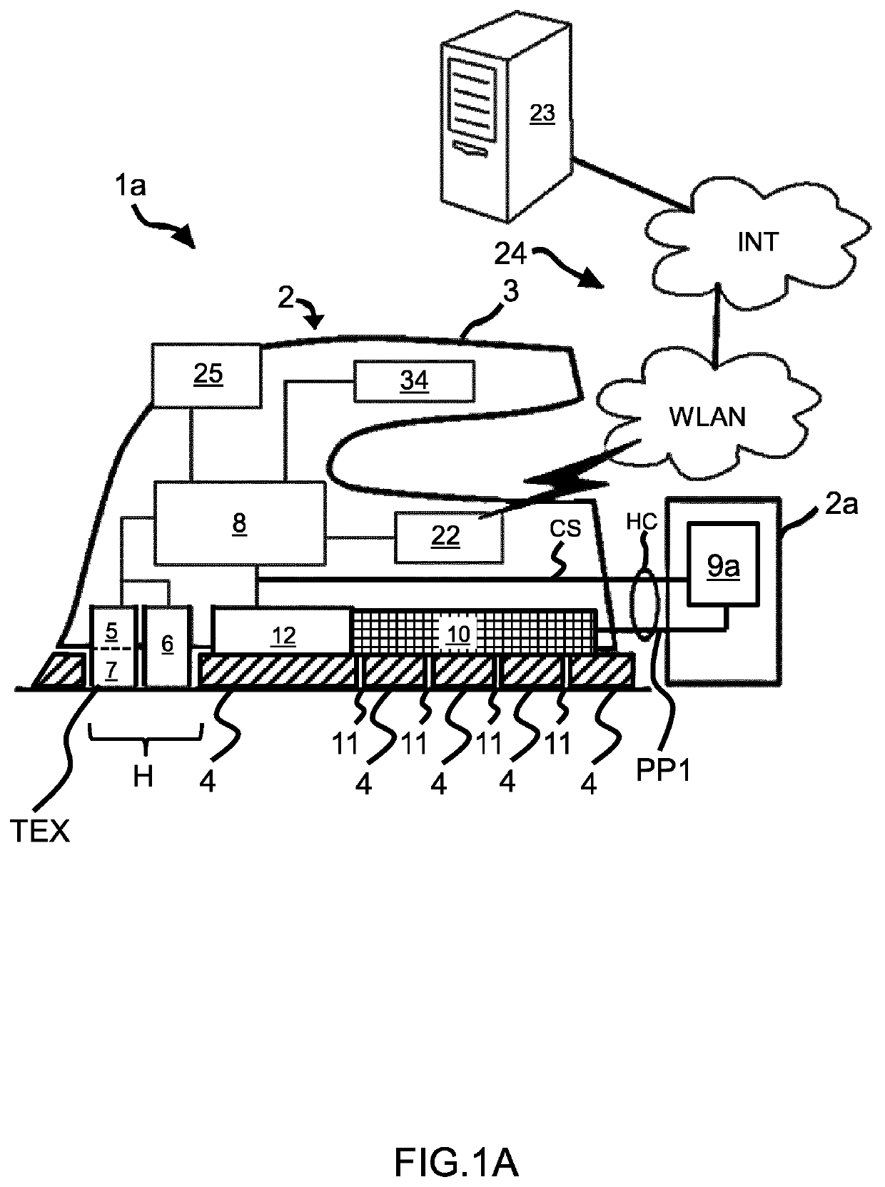
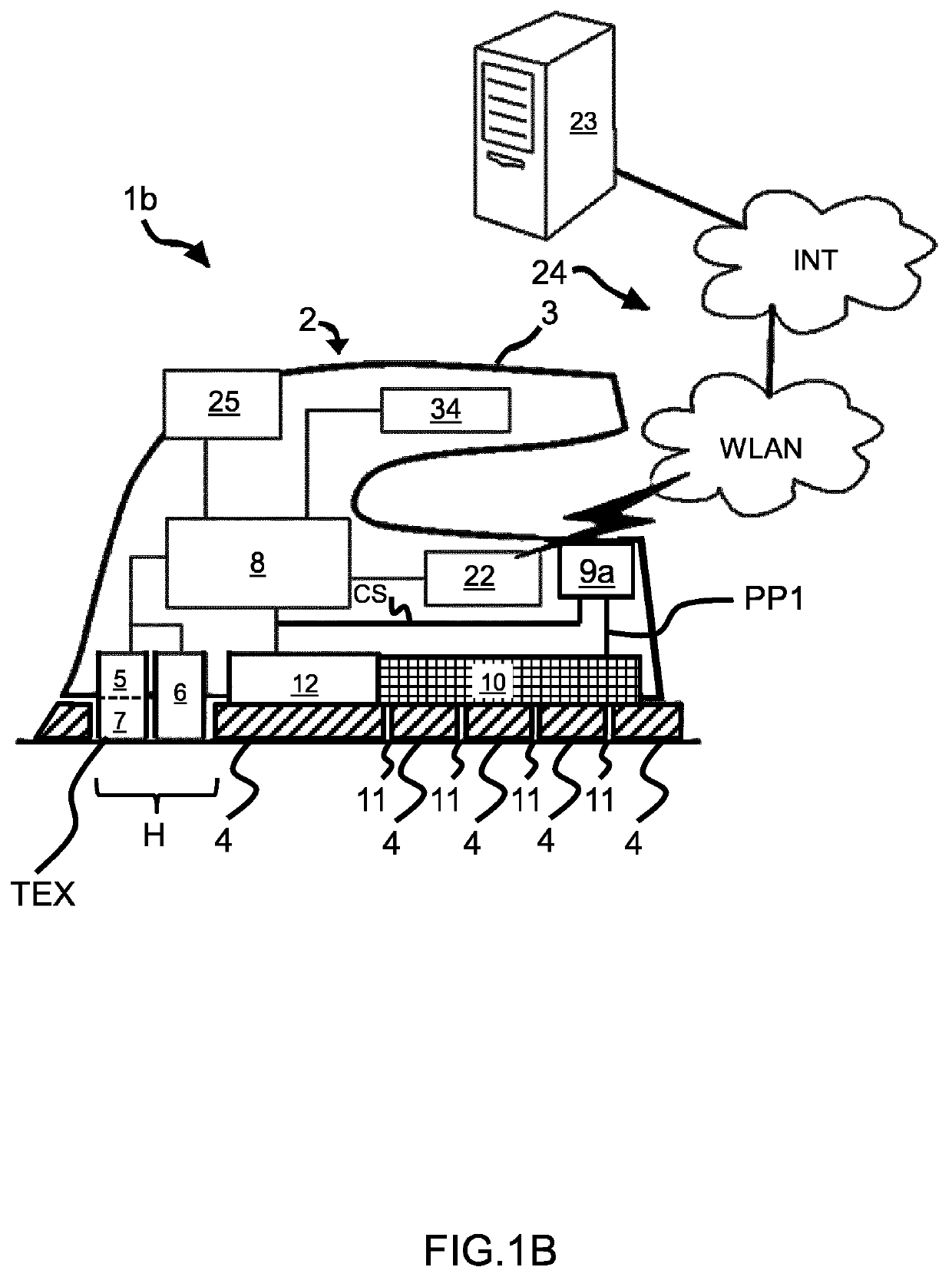
[0109]this invention is as shown in FIG. 9A where two electro-valves V1 and V2 are connected in series along the first pipe PP1.

[0110]The valve V1 in this embodiment is a standard electro-valve with one open (ON) and one closed (OFF) position. The open / close states of the valves V1 and V2 are controlled by control signal CS from the control unit 8.

[0111]The valve V2 in this embodiment is a customized electro-valve which does not have a real closed position. For valve V2, it has a large diameter (for example 4 mm) when being in open (ON) position, and a small diameter orifice (for example 2 mm) when being in closed (OFF) position.

[0112]The valve V1 controls steam on / off (release steam / not release steam), while valve V2 controls high (when ON) steam rate and low steam rate when OFF.

[0113]The different combinations and the resultant steam rates at the exit of the first pipe PP1 are listed in the below table 1:

[0114]

TABLE 1V1 State(Controls release of steam)On (Open)Off (Close)V2 StateO...

second embodiment

[0117]this invention is as shown in FIG. 9B, where two electro-valves (V1 and V2) are connected in parallel. Valves V1 and V2 in this embodiment can have the same orifice diameter or different orifice diameters depending on the requirements of the application.

[0118]Different steam rates at the exit of the first pipe PP1 can be obtained using a combination of E-valve states. This is shown in the below table 2:

[0119]

TABLE 2V1 State(Small - 2 mm orifice)On (Open)Off (Close)V2 StateOn (Open)High SteamMedium Steam(Large - 3 mmOff (Close)Low SteamNo Steamorifice)

[0120]The third embodiment of this invention is as shown in FIG. 9C. In this embodiment, valves V1 and V2 are the same as V1 and V2 in second embodiment except that they are built into a single housing SH1 as one component. The high steam rate and low steam rate are delivered in the same manner as in the second embodiment.

third embodiment

[0121]this invention reduces the amount of external tube connections, reducing the size of the E-valve configuration required to deliver this function.

[0122]Another benefit of the third embodiment is the reduction in condensation of steam to water in the E-valve configuration during the start of ironing or if the steam function has not been triggered for an extended period of time, thus reducing carryover water, which can result in a so-called “spitting” problem at the steam vents 11 of the heatable soleplate 4. This is due to the reduction of the overall thermal mass of the E-valve configuration.

[0123]The fourth embodiment of this invention is as shown in FIG. 9D. In this embodiment, valves V1 and V2 are the same as valves V1 and V2 in the first embodiment except that they are built into a single housing SH2 as one component. The high steam rate and low steam rate are delivered in the same manner as in the first embodiment.

[0124]The benefits of size reduction of E-valve configurati...


PUM


Abstract

The invention relates to a method of operating a textile treatment device comprising a heatable soleplate intended to be in contact with a textile for treating the textile. The method comprises a first step (1001) of setting a first temperature target for the heatable soleplate, and a step (1002) of detecting movement of said textile treatment device. If the step (1002) of 5 detecting movement did not detect any movement of said textile treatment device during more than a given first time duration, a step (1004) of actively decreasing the temperature of the heatable soleplate (4) up to reaching a first given temperature having a value below said first temperature target.

Description

CROSS REFERENCE TO RELATED APPLICATIONS[0001]This application is the U.S. National Phase application under 35 U.S.C. § 371 of International Application No. PCT / EP2018 / 086450 filed Dec. 21, 2018, published as WO 2019 / 122275 on Jun. 27, 2019, which claims the benefit of European Patent Application Number 17210086.9 filed Dec. 22, 2017. These applications are hereby incorporated by reference herein.FIELD OF THE INVENTION[0002]The invention relates to the field of garment care, in particular to a method of operating a textile treatment device.BACKGROUND OF THE INVENTION[0003]It is known that ironing devices are provided with temperature sensors. The temperature sensors are used to control operation of the ironing device and to avoid damaging the textile (of the garments) due to inappropriate operating parameters. If the user uses the ironing device for treating different textiles, it is necessary for the user to manually adjust at least one setting, in particular the temperature of the ...

Claims


Application Information

Patent Timeline
Patent Type & Authority Patents(United States)
IPC IPC(8): D06F75/26D06F75/14D06F75/22G06N3/04G06N3/08D06F87/00G05B13/02G06K9/62H04N5/225G05B19/4155D06F34/18D06F75/12G06K9/20D06F75/38D06F103/06
CPCD06F75/26D06F34/18D06F75/12D06F75/14D06F75/22D06F87/00G05B13/027G05B19/4155G06K9/209G06K9/2027G06K9/6253G06K9/6267G06N3/04G06N3/08H04N5/2253D06F75/38D06F2103/06G05B2219/45196D06F73/00D06F34/05D06F2105/58D06F2105/10D06F2105/48D06F2101/06D06F2105/52D06F2105/28D06F2105/40G06F18/24G06F18/40H04N23/54G06V10/141G06V10/147
Inventor KONG, XIN XIANDE BRUIJN, FREDERIK JANGEBRE, BINYAM GEBREKIDANPANG, YEN LENGKHNG, KENNYVAN BREE, KARL CATHARINATAN, BOON TECKVAN ACHT, VICTOR MARTINUS GERARDUSJIANG, YONGSIN, HEE POHVALIYAMBATH KRISHNAN, MOHANKUMARKAHYA, ORHANMEHENDALE, ADITYASCHMEITZ, HAROLD AGNES WILHELMUSZNAMENSKIY, DMITRY NIKOLAYEVICHWISMANS, ANTONIUS JOHANNES JOSEPHCONSOLI, SERGIOBIJL, PETRARAS, ARNOLDUS JOHANNES MARTINUS JOZEPHCHIAH, YAO HEAN
Owner VERSUNI HLDG BV
Learn More