
Light emitting apparatus, back light unit and display apparatus

Inactive Publication Date: 2016-04-21
BOE TECH GRP CO LTD +1
View PDF5 Cites 2 Cited by
  • Summary
  • Abstract
  • Description
  • Claims
  • Application Information

AI Technical Summary

Benefits of technology

This patent describes an improved light emitting apparatus that can solve problems such as poor rotation and unstable connections. The apparatus comprises a middle component with a recess and protrusion, which can be connected to other components by corresponding protrusion and recess so that they can rotate relative to each other. The middle component can be adjusted to different lengths to meet different needs. The apparatus also has arcuate portions in the recess and protrusion, which improve the rotation effect and make the connection between components more stable and reliable. The luminance at two ends of the apparatus can be enhanced. The invention can be used in a back light unit to achieve a curved surface display at a relatively low cost with a high yield.

Problems solved by technology

However, due to complexity of technology and relatively low yield, the development cost of the curved surface display screen is relatively high, and thus its application is limited.
Therefore, when such an integrated LED bar is applied to a back light unit of a curved surface display apparatus, the image quality of the curved surface display apparatus will be limited.
In addition, failure of one LED in the integrated LED bar may lead to malfunction of the whole LED bar, which causes an inconvenient maintenance of the back light unit and results in a relatively high cost of use of the display apparatus.

Method used


Image

  • Light emitting apparatus, back light unit and display apparatus
  • Light emitting apparatus, back light unit and display apparatus
  • Light emitting apparatus, back light unit and display apparatus

Examples


Embodiment Construction

[0027]In the following, the light emitting apparatus according to embodiments of the present invention will be explained with reference to the drawings by way of examples. The drawings are schematic and are not drawn in scale. The drawings are only used for explaining the embodiments of the present invention rather than limiting the protection scope of the present invention.

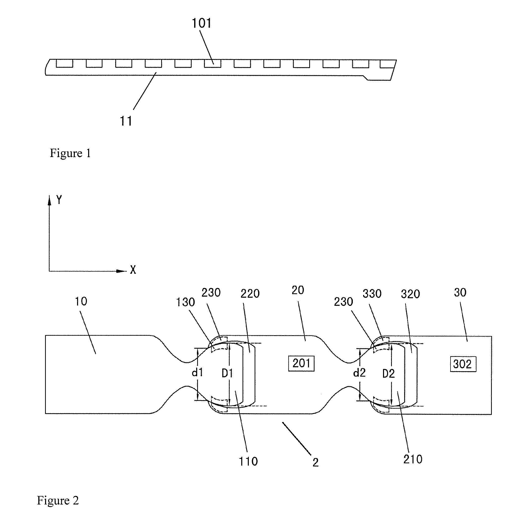
[0028]The inventor has recognized that the design and development of the existing curved surface display apparatus mainly focus on design of the screen of the display apparatus into a curved surface form. However, such design and development of a curved surface screen may result in complexity of technology and a relatively low yield, and also results in a relatively high cost of development. On the other hand, when the existing integrated light emitting apparatus e.g. the LED bar (FIG. 1) is applied to a curved surface display apparatus, the image quality of the curved surface display apparatus will be affected. ...


PUM


Abstract

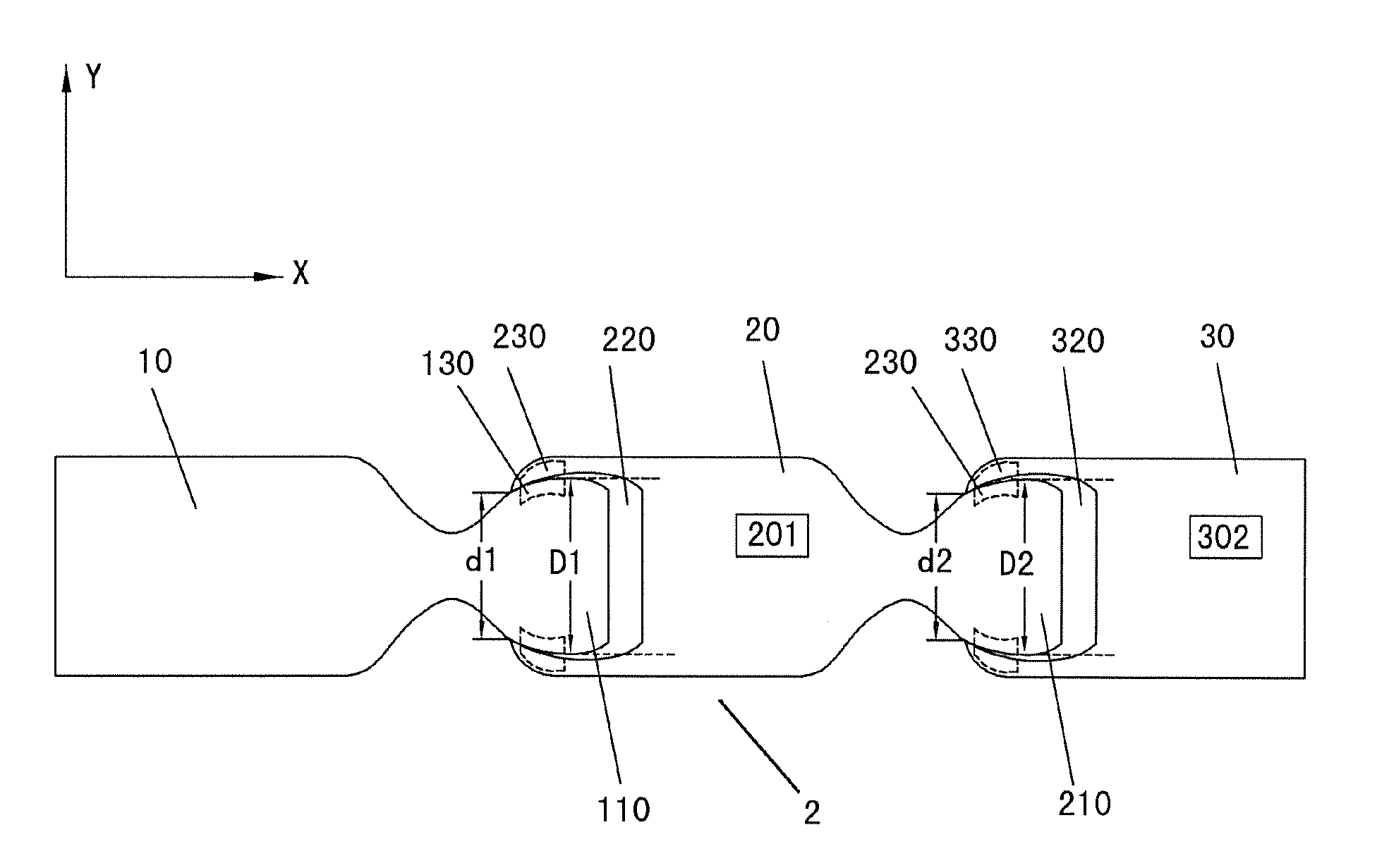
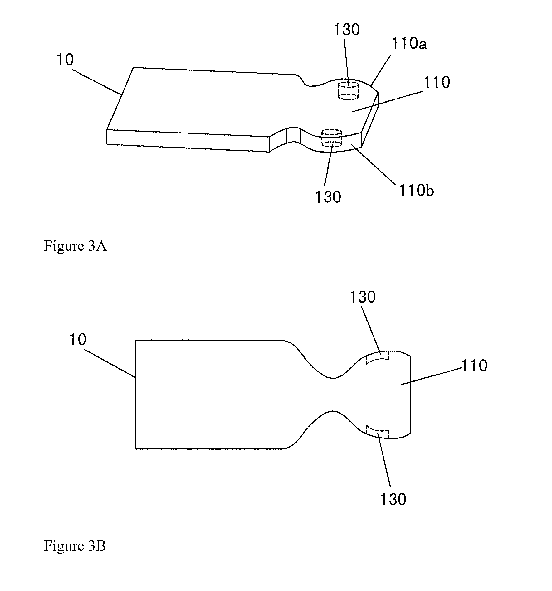
This disclosure provides a light emitting apparatus, the apparatus may comprise a middle component, a first end component and a second end component. The middle component may comprise a light emitting device and the middle component has a recess and a protrusion at its two ends respectively. One of the first and second end components has a recess, and the other of the first and second end components has a protrusion. The middle component can be connected with the first and the second end components respectively by corresponding protrusion and recess so that adjacent components can rotate relative to each other in a plane perpendicular to a light exit direction of the light emitting device. The light emitting apparatus can be applied to a back light unit of a display apparatus to realize curved surface display of the display apparatus.

Description

RELATED APPLICATIONS[0001]The present application claims the benefit of Chinese Patent Application No. 201410543742.9, filed Oct. 15, 2014, the entire disclosure of which is incorporated herein by reference.FIELD OF THE INVENTION[0002]This disclosure relates to a light emitting apparatus, more specifically, a light emitting apparatus that can be applied to a back light unit of a display apparatus.BACKGROUND OF THE INVENTION[0003]A display apparatus such as liquid crystal display (LCD), organic light emitting diode (OLED) display is one of the most widely used apparatus currently. In addition to the conventional plane display apparatus, some curved surface display products also appear in the market for meeting requirements of different consumers and different occasions. The existing curved surface display apparatus is mainly achieved by designing the screen of the display apparatus into a curved surface form. Therefore, the design and research on the curved surface display mainly foc...

Claims


Application Information

Patent Timeline
IPC IPC(8): F21S4/00
CPCF21S4/008H01L33/483H01L33/62H01L33/48G02F1/133603G02F1/133608G02F2201/16F21S4/28
Inventor LIU, JIEGAI, XINLI, DONGXI
Owner BOE TECH GRP CO LTD
Learn More