Electronic package assembly

Inactive Publication Date: 2005-01-11
NXP USA INC
View PDF6 Cites 29 Cited by
  • Summary
  • Abstract
  • Description
  • Claims
  • Application Information

AI Technical Summary

Benefits of technology

In this way an electronic package assembly is provided which has improved integration and good thermal management.

Problems solved by technology

A problem with existing combined logic / power packages is that the high power requirements of the high-sided switch do not easily facilitate integration with low power logic integrated circuits.
The high currents involved preclude the use of conventional wire bond techniques, and the thermal management of heat dissipation presents further problems.

Method used


Image

  • Electronic package assembly
  • Electronic package assembly
  • Electronic package assembly

Examples


Embodiment Construction

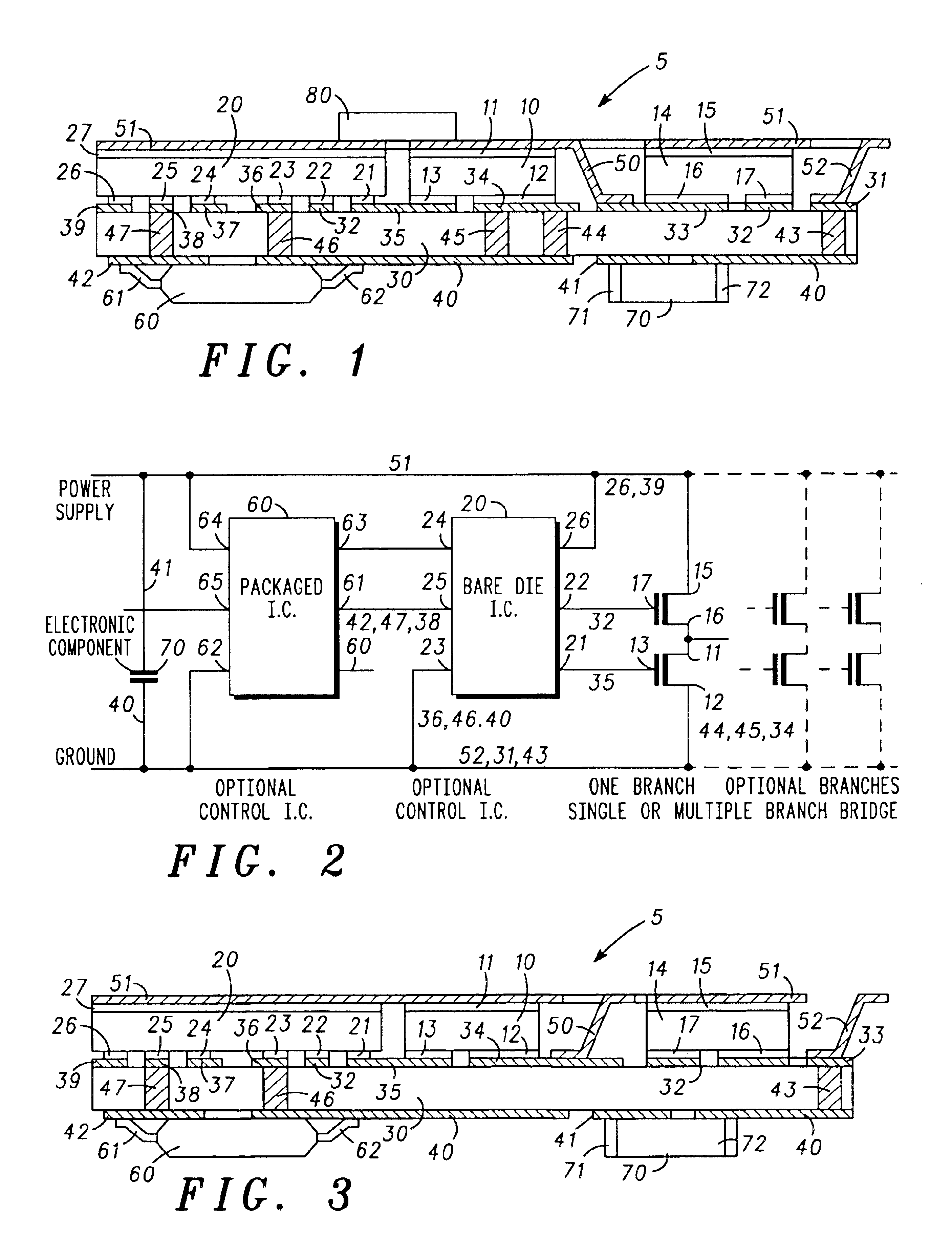
Referring to FIG. 1, there is shown an electronic package assembly 5 comprising double-sided leadless components (10, 14, 20) a printed circuit substrate 30, a lead frame comprising first (50) second (51) and third (52) elements and other electronic components (60, 70).

The substrate 30 is a multi-layered substrate of dielectric material and has top and bottom faces. The top face has a first set of printed circuit patterns 31-39, which facilitate connection of the substrate 30 to the double-sided leadless components (10, 14, 20) and also to the selected elements of the lead frame (50 and 52) to be further described below.

The substrate 30 also has a second set of printed circuit patterns 40-42 on the bottom face thereof. These second patterns 40-42 facilitate connection of the substrate 30 to the other electronic components (60, 70) which may be single or multiple packaged components. The first component 60 may be a packaged integrated circuit having electrical terminals 61 and 62 in ...


PUM


Abstract

An electronic package assembly includes a number of semiconductor devices with first and second sides. A printed circuit substrate has a number of printed circuit patterns bonded to conductive pads of the first sides of the devices. A metal leadframe includes leads which provide external connections for the package assembly, and also includes a non-lead island portion bonded to conductive pads of the second sides of the devices. In this way the island portion of the leadframe forms an interconnection between the second sides of the devices.

Description

FIELD OF THE INVENTIONThis invention relates to an electronic package assembly and preferably but not exclusively to an electronic package assembly incorporating a power transistor.BACKGROUND OF THE INVENTIONIn many electronic applications, particularly in automotive applications, power and logic devices are used in conjunction with each other, to perform a single function.For example, an electric motor for operating an automatic sunroof or a window of a vehicle is typically actuated by a high-sided switch formed by power transistors. In order to reduce power consumption, the high-sided switch is ideally placed as close as possible to the electric motor, thus keeping the length of high current paths to a minimum and hence reducing unnecessary power losses.Typically the driver of a vehicle may prefer to operate a separate switch on the dashboard of the vehicle, which then sends a (low-power) signal to the high-sided switch, in order to actuate it. Therefore a certain amount of logic ...

Claims


Application Information

Patent Timeline
IPC IPC(8): H01L23/48H01L23/498H01L25/16H05K1/18
CPCH01L23/49861H01L25/16H05K1/181H01L2924/0002H01L2924/00
Inventor TRIANTAFYLLOU, MARKOSSPECKS, WILLESCOFFRE, CLAUDE
Owner NXP USA INC
Why Eureka
Try Eureka