
DNA base sequencing system

Inactive Publication Date: 2005-01-11
HITACHI LTD
View PDF17 Cites 185 Cited by
  • Summary
  • Abstract
  • Description
  • Claims
  • Application Information

AI Technical Summary

Benefits of technology

In the present invention, a reaction cell (reaction chamber) and a dNTP-supply route are formed into a module by microprocessing such that the dNTP can be readily supplied by pressurization, whereby the physical size of the required apparatus or system can be minimized. Further, a necessary and sufficient amount of dNTP and reagents can be injected into the reaction area by an efficient supplying method using a simple sample-introducing means instead of an ink jet system or the like, which makes the apparatus small, light and low-cost.
Longer DNAs can be sequenced and analyzed by carrying out a sufficient and thorough reaction. Therefore, the structure of the reaction vessel is devised such that the reaction chamber is in contact with a vibrating element to thoroughly mix added dNTP with a reaction solution. The reaction efficiency can be increased by stirring the injected dNTP.

Problems solved by technology

However, a big problem remains to be solved: how to quickly analyze a large amount of DNA samples.
One problem in the current pyrosequencing method, in which ink jet nozzles are used for dNTP injection, is that it requires a considerably large space for the apparatus including a control part for the ink jet nozzles or the like.
Another problem is that the target DNA to be provided as a sample in the reaction vessel has to be a single strand, which requires extra labor for the sample preparation.
Further, sequencing is not possible in the presence of DNAs, which undergo complementary strand synthesis, other than the target DNA.
However, for practical use of these systems, several technical problems remain to be solved: (1) how to implement a simple and inexpensive compact apparatus, (2) how to minimize the time required for sample preparation, and how to analyze various samples simultaneously in a simple way, and (3) how to uniformly carry out reactions to increase the reaction efficiency.

Method used


Image

  • DNA base sequencing system
  • DNA base sequencing system
  • DNA base sequencing system

Examples


example 1

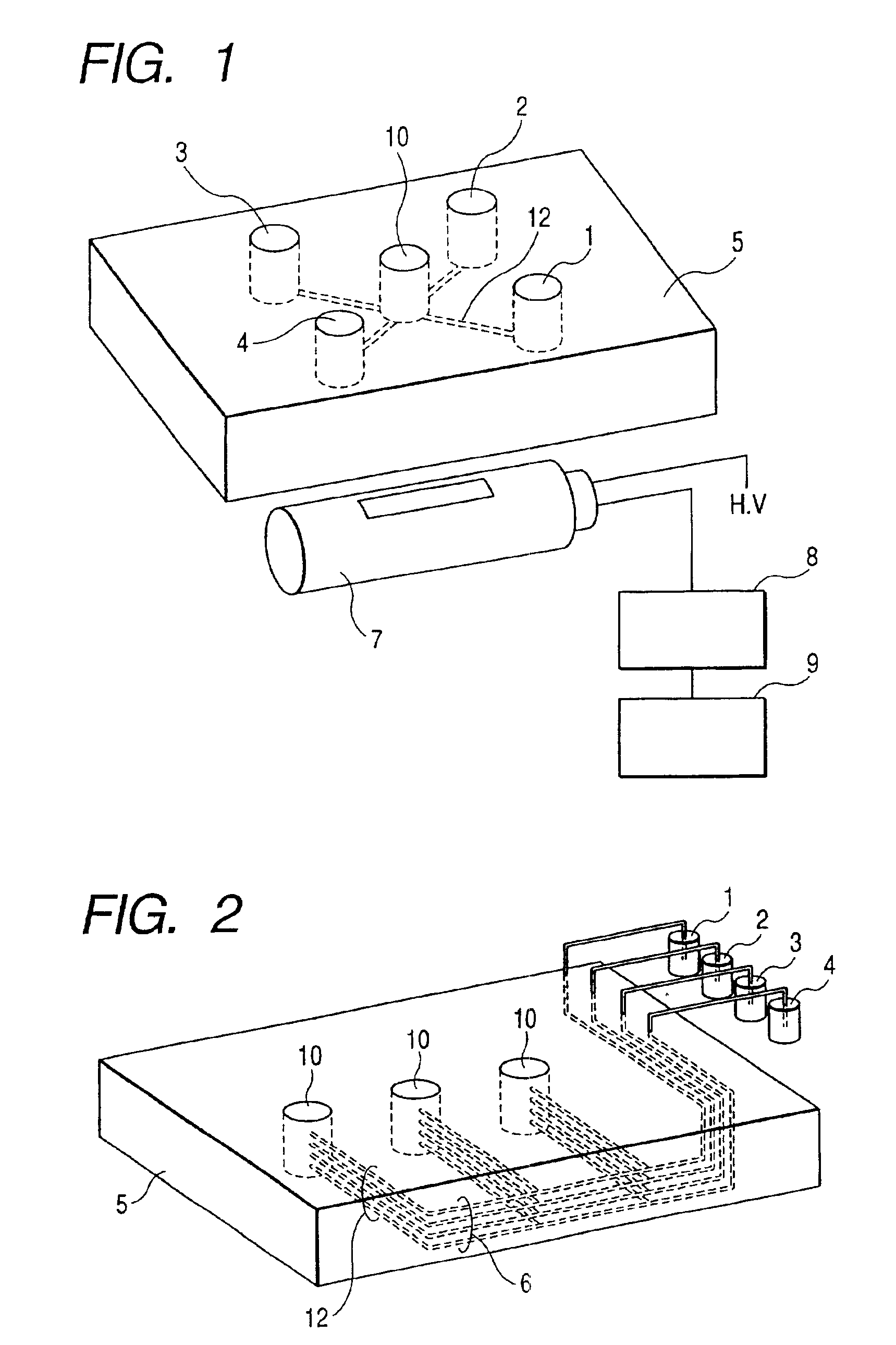
FIG. 1 shows a structure example of Example 1 according to the present invention, which is a pyrosequencing device (DNA base sequencing system) having one reaction vessel and dNTP reagent reservoirs. A reaction chamber module comprises a reaction chamber (reaction vessel) 10 and reagent reservoirs 1, 2, 3 and 4 each holding one of four kinds of dNTP, all formed on a device board 5. The reaction chamber 10 and each reservoir are connected by capillaries 12 for reagent introduction, through which dNTP from each reagent reservoir is supplied into the reaction vessel for use in the reaction. dNTP is allowed to flow into reaction chamber 10 by pressurizing the liquid surface of each reagent reservoir. It is necessary to suppress a backward flow of the reaction solution and to prevent flow of the reagents into other sites due to a slight difference in the level of liquid surface. Therefore, capillaries having an inner diameter of less than 0.1 mm or a cross section of less than 0.01 mm2 a...

example 2

FIG. 5 is a structure example of Example 2, showing one type of pyrosequencing device (DNA base sequencing system) in which dNTP is injected into a reaction vessel via capillaries from the upper part. In Example 2, reagents are injected from the upper part of the reaction chamber 10. The reaction chamber module of Example 2 is composed of the reaction vessel (reaction chamber) 10 formed on a device board 5 and a cover (reagent supply unit) 11 which is separable from the device board 5. The upper part of the reaction chamber 10 is covered with the cover 11 which is equipped with reagent-introducing narrow tubes 6 and reagent-introducing capillaries (capillaries) 12. The capillaries 12 in Example 2 have an increased inner diameter of 0.2 mm since the part of the capillaries in contact with the reaction chamber 10 is longer than that in Example 1. The conductance of the capillary having an inner diameter of 0.2 mm for the reagent solution determines the injection speed of the solution....

example 3

FIG. 7 is a structure example of Example 3 of the present invention, showing a conjugate-type reaction chamber module of a DNA sequencing system, in which a multiple number of reaction vessels and a multiple number of reagent reservoirs are installed and reagents are supplied into reaction vessels using narrow tubes formed by microprocessing or the like.

In the example of the conjugate-type reaction chamber module shown in FIG. 7, reaction reagents are supplied from the lower part of the reaction chambers 10. In the conjugate-type reaction chamber module, an upper board 14 having a multiple number of holes to be made into reaction chambers 10 are formed and the lower board 15 comprising a multiple number of reagent reservoirs 1, 2, 3, 4, 1′, 2′, 3′ and 4′ and reagent-introducing capillaries (narrow grooves) 13 are formed and conjugated such that the multiple number of reaction chambers 10 are formed by the conjugation between the upper board 14 and the lower board 15. A reagent reser...


PUM

PropertyMeasurementUnit
Diameteraaaaaaaaaa
Diameteraaaaaaaaaa
Diameteraaaaaaaaaa

Abstract

The present invention provides a DNA base sequencing system having a compact, simple and convenient structure.In one embodiment of the present invention, a reaction chamber module for pyrosequencing in which a multiple number of reaction vessels (reaction chambers) 10 and reagent-introducing narrow tubes 6 are integrated is formed in a device board 5. Reagents held in reagent reservoirs 1, 2, 3 and 4 mounted separately from this reaction chamber module are introduced into the reaction vessels 10 via reagent-introducing narrow tubes (capillaries) 6. The reagent-introducing narrow tubes (capillaries) 6 at the area of 2 cm from the reaction vessels 10 are structured with narrow capillaries having an inner diameter of about 0.1 mm and the conductance of these capillaries for the reagent solution determines the injection speed of the solution.Using the present invention, many kinds of DNAs can be analyzed simultaneously.

Description

BACKGROUND OF THE INVENTIONThe present invention relates to assays and analyses of genes or DNAs relating to gene diagnoses, gene therapies, and production of various substances by genes, or the like. In particular, the present invention relates to improvement of pyrosequencing and systems thereof, namely DNA base sequencing methods or sequence monitoring methods and DNA base sequencing systems or sequence monitoring systems.The progress of the human genome-mapping project is prompting a trend towards conducting diagnoses of diseases and producing useful novel substances at the gene level by reading DNA sequences. However, a big problem remains to be solved: how to quickly analyze a large amount of DNA samples. Although fundamental DNA base sequence data have been almost completely revealed by the genome mapping, it is necessary to compare sequences of various samples with those of standard samples previously sequenced, in order to study sequences of these DNAs and gene functions. T...

Claims


Application Information

Patent Timeline
IPC IPC(8): C12Q1/68C12M1/00G01N27/447C12M1/34C12N15/09
CPCC12Q1/6869C12Q2565/537C12Q2565/301
Inventor KAMBARA, HIDEKIZHOU, GUOHUAMIYAHARA, YUJI
Owner HITACHI LTD
Learn More