Multi-pitch improved ridge-seal for tiled roofs

a tiled roof and multi-pitch technology, applied in the field of roof construction, can solve the problems of uneven roof pitch, inconvenient installation of tiled roofs, and inability to meet the needs of different roof types,

Inactive Publication Date: 2005-01-11
VERDE IND
View PDF11 Cites 4 Cited by
  • Summary
  • Abstract
  • Description
  • Claims
  • Application Information

AI Technical Summary

Benefits of technology

In a preferred embodiment of the present invention a ridge seal molding having a length and width, comprising a back section for nailing to a ridge beam, providing thereby a continuous contact along the length to the ridge beam; and a front section formed at a

Problems solved by technology

Because tiles are rigid, three-dimensional shapes, intimate fit between one tile and another in an overlapping arrangement is less than perfect.
For the same reason, sealing and protecting interfaces between one surface area on a roof and another, such as ridges and valleys, is often a problem.
A persistent problem with developing and manufacturing ridge seals, which are typically relatively thin plastic moldings, is that roof pitches vary widely, and it is often necessary to make several different models of ridge seals to accommodate the range of pitches that may be encountered.
Another problem is that it is desirable that the lower edges of ridge seals conform to the shape of adjacent tiles and firmly and intimately contact the tiles below the ridge line, to effectively bar wind and water from entering the ridge area under the cap tiles.
Still another problem proceeds from the fact that the cap tiles lie on the adjacent, repeating peaks across adjacent tiles, leaving very apparent openings under the cap tiles.
The appearance of mudding in is typically desirable to homeowners, but is not efficient, is time-consuming, and is also less than durable.
Over time the concrete used chips away, and may slide down the tiles creating a debris problem, may clog drains, and may even pose a safety hazard.

Method used


Image

  • Multi-pitch improved ridge-seal for tiled roofs
  • Multi-pitch improved ridge-seal for tiled roofs
  • Multi-pitch improved ridge-seal for tiled roofs

Examples


Embodiment Construction

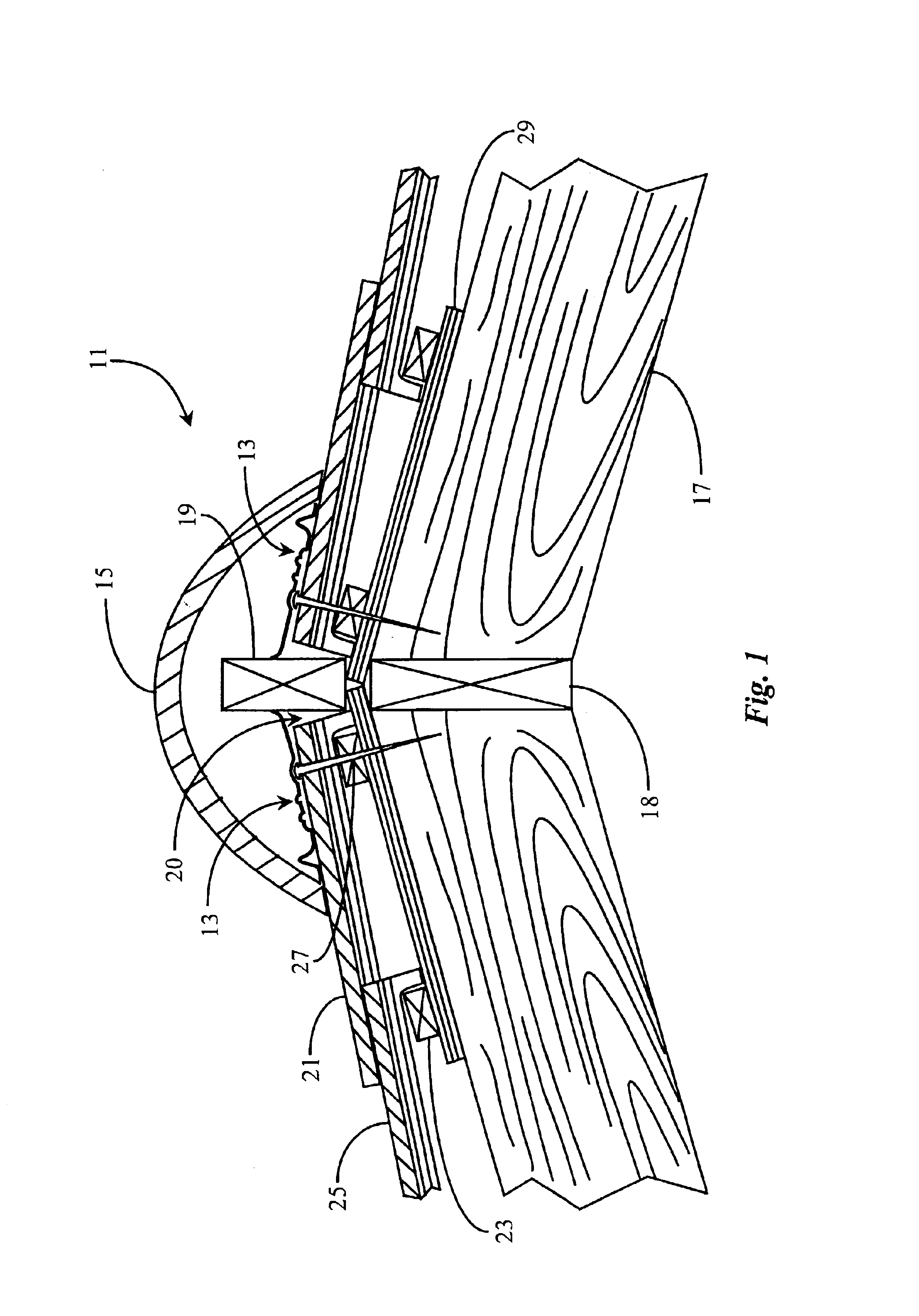
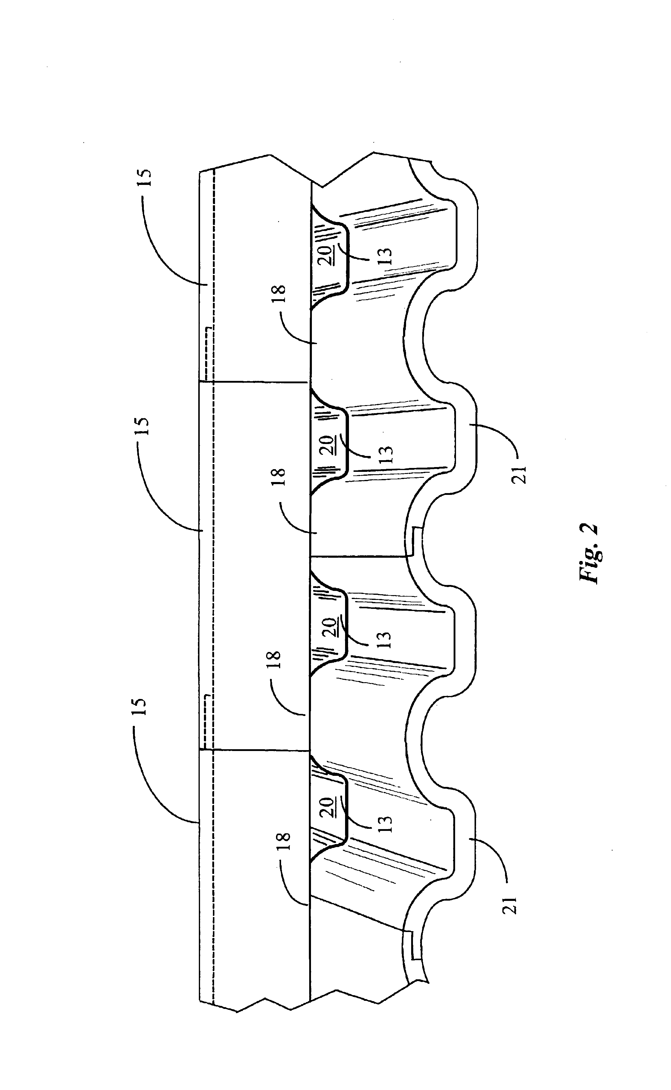
FIG. 1 is a cross-sectional view of a ridge area 11 of a tiled roof illustrating installed ridge-seals 13 according to an embodiment of the present invention. Roof area 11 is typical of a tiled-roof ridge. Wooden roof beams 17 are joined at the ridge at an angle by way of ridge beam 18. This forms an underlying roof-structure having a particular pitch that may vary considerably from roof to roof.

Wooden panels 29, typically plywood, are laid over beams 17 and nailed in place to form a support surface for accepting a tile roof. Wooden cross-members 23, sometimes termed bats, are then strategically located and nailed to panels 29 to form a series of retainers over which tiles may be laid to form the tile roof. In some cases the plywood panels are not installed and the bats are nailed directly to the roof beams. Tiles 25 are hung adjacent to one another beginning at the lower edges of each roof area and overlapped in a series of rows with cross-members 23 supporting and guiding the loca...


PUM


Abstract

A ridge seal molding has a back section for nailing to a ridge beam, and a front section formed at an angle to the back section and having a shape in the direction of the length to substantially continuously contact adjacent tiles along a front edge. In various embodiments there are one or more reinforcing ribs in the general direction of the width of the molding. In some embodiments two or more nail positions are marked in the back section for use with roofs of a specific pitch range, UV resistant material to provide improved durability, a receptacle groove formed along the front edge and opening downward toward the tile, such that a sealing material may be placed in the groove prior to installing the ridge seal molding to a roof ridge, and panels simulating a concrete surface for a mudded-in look. A system is provided as well for dedicating ridge seals to specific pitch ranges.

Description

FIELD OF THE INVENTIONThe present invention is in the field of roofing construction and pertains particularly to methods and apparatus for sealing ridge terminations on a tiled roof from effects of weather and exposure.BACKGROUND OF THE INVENTIONIn the field of roofing construction, one of the most popular and sought-after coverings is tile. A tile roof is a roofing system comprising a plurality of individual tiles made of fired clay, or, more recently a composite material. Tiles for such roofing construction are shaped and arranged on a roof to lie in overlapping fashion so as to completely cover a roof in a manner that rainwater will drain from one tile to another off the roof area.Because tiles are rigid, three-dimensional shapes, intimate fit between one tile and another in an overlapping arrangement is less than perfect. For the same reason, sealing and protecting interfaces between one surface area on a roof and another, such as ridges and valleys, is often a problem. Sealing ...

Claims


Application Information

Patent Timeline
IPC IPC(8): E04D1/00E04D1/36
CPCE04D1/36
Inventor REEVES, ERIC NORMAN
Owner VERDE IND
Why Eureka
Try Eureka