
Fiber optic sensor system and method for measuring the pressure of media

a fiber optic sensor and pressure sensor technology, applied in the field of pressure sensing, can solve the problems of huge system cost and weight, impediment to non-optical pressure sensors, so as to prevent contamination of sensing media, minimize or eliminate problems

Inactive Publication Date: 2005-01-04
AIRAK
View PDF3 Cites 39 Cited by
  • Summary
  • Abstract
  • Description
  • Claims
  • Application Information

AI Technical Summary

Benefits of technology

It is a further object of the invention to provide an optical system and method for measuring pressure which prevents self-ignition through electrical current discharge.
It is a further object of the invention to provide an optical system and method for measuring pressure which avoids the exposure of organic adhesives to the sensing media via the sensor head, thereby preventing contamination of the sensing media.
It is a further object of the invention to provide an optical system and method of measuring pressure which minimizes or eliminates problems associated with long-term drift of the sensor element.

Problems solved by technology

A major impediment to non-optical pressure sensors arises from the requirement of electrical current flow at the sensor location.
Most anti-explosion countermeasures involve changing the environment that contains the media—double insulating the container and placing the sensor in between the two vessels—that often results in tremendous additional cost and weight to the system.
Another significant impediment to non-optical pressure sensors is the close proximity requirement between the sensor diaphragm and the signal processing electronics.
In most non-optical systems, the resolution, or the smallest detectable change in pressure, is limited by electrical noise that is induced into the system due to generally harsh operating environments.
Typically, (3) is implemented, resulting in increased weight due to the shielding solution as well as added complexity in co-locating the sensor and signal processing functions.
For small-volume pressure measurements this outgassing phenomenon causes the total pressure within the sensor vessel to increase, contributing significantly to the overall error of the system.
Additionally, in many instances, these gaseous organic compounds can react with the media they are sensing, causing unwanted chemical reactions, potentially giving rise to self-ignition.
Another major impediment to non-optical pressure sensor methodologies is the long-term stability of such sensors.
If the input power to the system fluctuates significantly, the stability of the measurement system is adversely affected, requiring recalibration of the sensor element.
Furthermore, removing power from the system results in complete loss of the calibration reference; this also requires recalibration upon re-energizing the equipment.
Both of these scenarios prevent the long-term monitoring of an environment with respect to pressure.

Method used


Image

  • Fiber optic sensor system and method for measuring the pressure of media
  • Fiber optic sensor system and method for measuring the pressure of media
  • Fiber optic sensor system and method for measuring the pressure of media

Examples


Embodiment Construction

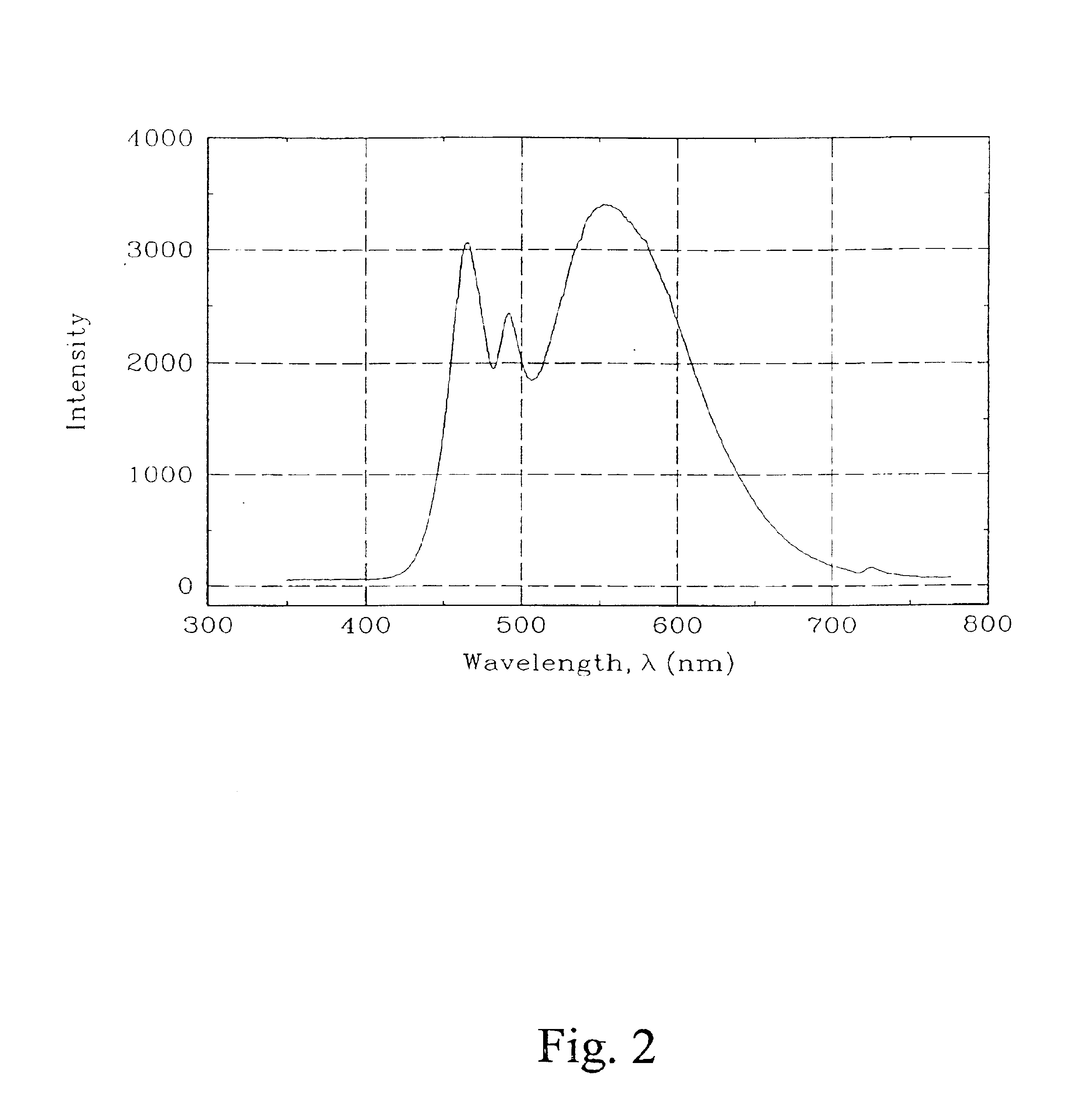
FIG. 1 shows a block diagram illustrating the overall operation of the hardware and software of the system in accordance with a preferred embodiment. Light, generated by a light emitting diode (LED) 100 and under the control of a LED driver system 101, is launched into one arm of a −3 dB single mode optical coupler (SMOC) 102. Correct operation of the system has been demonstrated using a white light LED (spectra provided in FIG. 2), a wide-band LED centered at 740 nm with a full-wave-half-maximum (FWHM) of 35 nm, and a super-luminescent LED (SLED) centered at 850 nm with a FWHM of 21 nm. The light energy, after traveling through the coupler 102, is attenuated by 3 dB and is sent simultaneously to a power monitoring photodiode 103 and to a fiber optic pressure sensor 104. The energy that falls upon the power monitoring photodiode 103 is used to regulate and stabilize the LED driver 101 current so that intensity fluctuations are kept to a minimum. The energy that travels to the fiber ...


PUM


Abstract

In a preferred embodiment, the invention provides a fiber optic pressure sensor apparatus which includes a light source, a reflective sensor diaphragm movable in accordance with pressure in a medium and an optical fiber coupled to the light source for delivering a first wavefront of light to the reflective sensor diaphragm. The optical fiber has an endface which is separated from the reflective sensor diaphragm by a gap, the endface receiving a second wavefront of light reflected from the reflective sensor diaphragm. The first and second wavefronts constructively and destructively interfere to create a modulated optical signal. A spectrometer is coupled to the optical fiber for converting the optical signal into a series of digital values, and means for analyzing the digital values is provided for obtaining a measurement of the pressure in the medium. An optical coupler is preferably provided for coupling the light source, the optical fiber, and the spectrometer. A power monitoring optical detector means may be coupled to the light source by the optical coupler. A graded-index lens may be coupled to the endface of the optical fiber. The angle between the endface and a longitudinal axis of the optical fiber may be formed to be between zero and 11 degrees. A sealed or vented sensor body may be provided. In sealed embodiments, organic adhesives are preferably used to seal the sensor body. The means for analyzing the digital values preferably includes means for recovering phase information from the modulated optical signal by taking a Fourier transform of the modulated optical signal. Sensor gap measurements are then derived from this phase information.

Description

This application is related to U.S. patent application Ser. No. 09 / 783,390 entitled “Fiber Optic Sensors and Methods Therefor,” filed Feb. 15, 2001, by inventors Paul G. Duncan et al., the entire disclosure of which is incorporated herein by reference. This application is further related to U.S. patent application Ser. No. 09 / 783,389 entitled “Apparatus and Method for Volumetric Dilatometry” filed Feb. 15, 2001 by inventors Paul G. Duncan, et al., the entire disclosure of which is incorporated herein by reference.This application includes material that is subject to copyright protection. The copyright owner has no objection to the facsimile reproduction by anyone of the patent disclosure, as it appears in the Patent and Trademark Office files or records, but otherwise reserves all copyright rights whatsoever.BACKGROUND OF THE INVENTION1. Field of the InventionThe invention relates in general to the field of pressure sensing, and in particular to optical pressure sensors for pressure...

Claims


Application Information

Patent Timeline
IPC IPC(8): G01L9/00G01J3/02G01J3/00
CPCG01J3/02G01L9/0077G01J3/0218
Inventor DUNCAN, PAUL GREMSCHRISTIAN, SEAN MICHAELSCHROEDER, JOHN ALAN
Owner AIRAK
Learn More