
Automatic picture tube cutting machine

a picture tube and cutting machine technology, applied in the manufacture of electrode systems, manufacturing tools, electric discharge tubes/lamps, etc., can solve the problems of affecting the work efficiency of workers, affecting the quality of work, so as to facilitate the movement of the picture tube to the center poin

Inactive Publication Date: 2005-01-04
YEH NENG KUEI
View PDF16 Cites 25 Cited by
  • Summary
  • Abstract
  • Description
  • Claims
  • Application Information

AI Technical Summary

Benefits of technology

Another objective of the invention is to offer an automatic picture tube cutting machine having a recessed frame fitted in the center portion of the transporting tray so that the curved screen of the picture tube may just contact the upper circumferential edge of the recessed frame, at the same time permitting the cutting device to easily move the picture tube to correct its center point.

Problems solved by technology

Therefore, if it is not properly treated, it pollutes the environment to bring danger to people's health.
1. Placing a picture tube on the work table is done completely by manual labor, it takes much time and work, especially in case of a heavy one, chances are that a picture tube may be broken by colliding with something hard carelessly, causing danger to workers.2. As picture tubes have various sizes, tungsten filament may have to be long enough for winding, and in addition, heating and cooling time may be different. So a worker should have some experience, or work efficiency may be low. And experienced workers may have to be paid high wages.

Method used


Image

  • Automatic picture tube cutting machine
  • Automatic picture tube cutting machine
  • Automatic picture tube cutting machine

Examples


Embodiment Construction

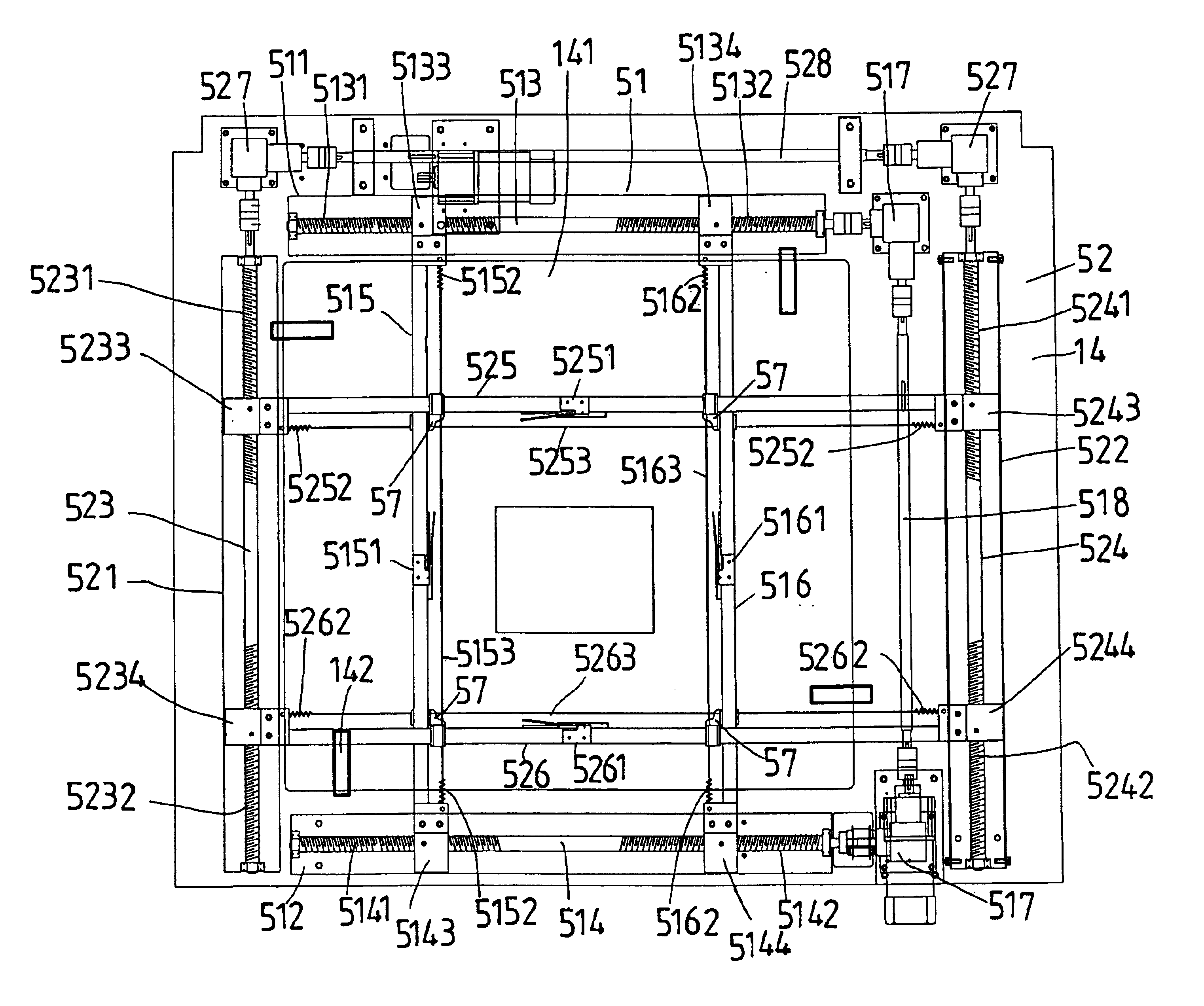
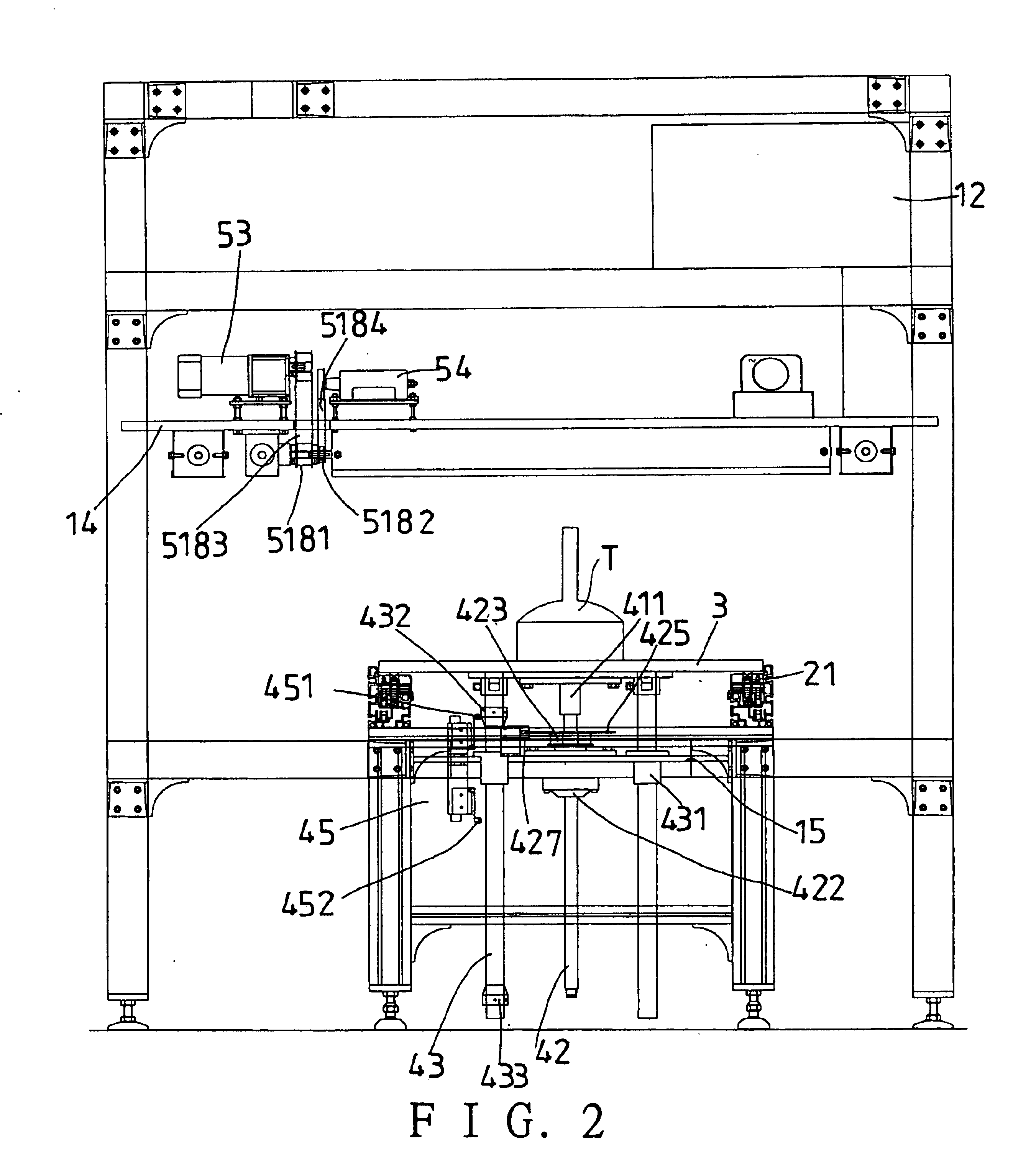
A preferred embodiment of an automatic picture tube cutting machine in the present invention, as shown in FIGS. 1, 2 and 3, includes a machine frame 1, a transporting machine 2, a transporting tray 3, a moving-up-and-down base 4 and a positioning and cutting device 5 as main components combined together.

The machine frame 1 has a preset height, a lateral rod 11, a water tank 12 and a controller 13 placed on the lateral rod 11, an upper flat plate 14 and a lower flat plate 15 below the lateral rod 11, the positioning and cutting device 5 fixed on the upper flat plate 14, the moving-up-and-down base 4 fixed on the lower flat plate 15. The upper flat plate 14 has a center hole 141 for a moving-up-and-down plate 41 of the moving-up-and-down base 4 with a picture tube placed on the plate 41 to move up therein, a plurality of nozzles 142 are positioned on a circumferential edge, connected to the water tank 12. The transporting machine 2 moves back and forth through a lower portion of the m...


PUM


Abstract

An automatic picture tube cutting machine is provided. The machine includes a transporting mechanism for transporting a tray carrying a picture tube into a moving-up-and-down base, which automatically adjusts the vertical position of the picture tube based upon its size. The machine also includes a positioning and cutting device wherein a plurality of clamp units cooperatively set tungsten heating filaments in contact with the picture tube to circumscribe that picture tube at a preset cutting height. Upon heating via the tungsten heating filaments and subsequent cool water quenching, the picture tube is broken at its circumscribed portion into separated front and rear stages.

Description

BACKGROUND OF THE INVENTIONThis invention relates to an automatic picture tube cutting machine, particularly to one automatically feeding material, measuring the size of a picture tube, positioning and cutting the picture tube.Nowadays, televisions have been widely used in homes, and a large number of them are discarded. Then it is very important to recycle luminescent powder painted in a picture tube, as luminescent powder is a material leading to grow cancer in a human body. Therefore, if it is not properly treated, it pollutes the environment to bring danger to people's health.In treating old picture tubes of televisions and computers, a front stage containing barium glass is first to be cut off a rear stage of lead glass, and then luminescent powder painted on an inner surface of the glass is sucked off by means of vacuum process, and then collected to be sealed in a container. Then it is sent to a qualified waste treatment factory to be hardened. However, cutting picture tubes ...

Claims


Application Information

Patent Timeline
IPC IPC(8): C03B33/095C03B33/00H01J9/52
CPCC03B33/095H01J9/52Y10S269/908Y10T225/304Y10T225/321Y02W30/82
Inventor YEH, NENG-KUEI
Owner YEH NENG KUEI
Learn More