
Device for inspecting hermetically sealed packages

a technology for hermetically sealed packages and devices, applied in the direction of material breakdown voltage, transportation and packaging, instruments, etc., can solve the problems of inability to operate, inconvenient decomposition or decomposition of contents, and inability to decompose or decay contents, etc., to increase the voltage applied

Inactive Publication Date: 2004-09-21
JOVEN ELECTRIC
View PDF4 Cites 20 Cited by
  • Summary
  • Abstract
  • Description
  • Claims
  • Application Information

AI Technical Summary

Benefits of technology

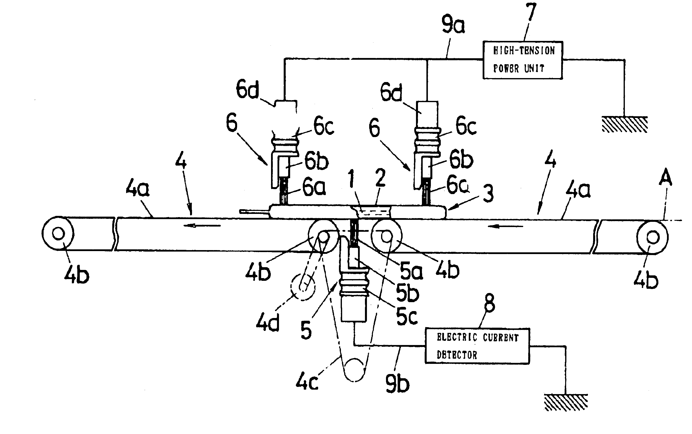
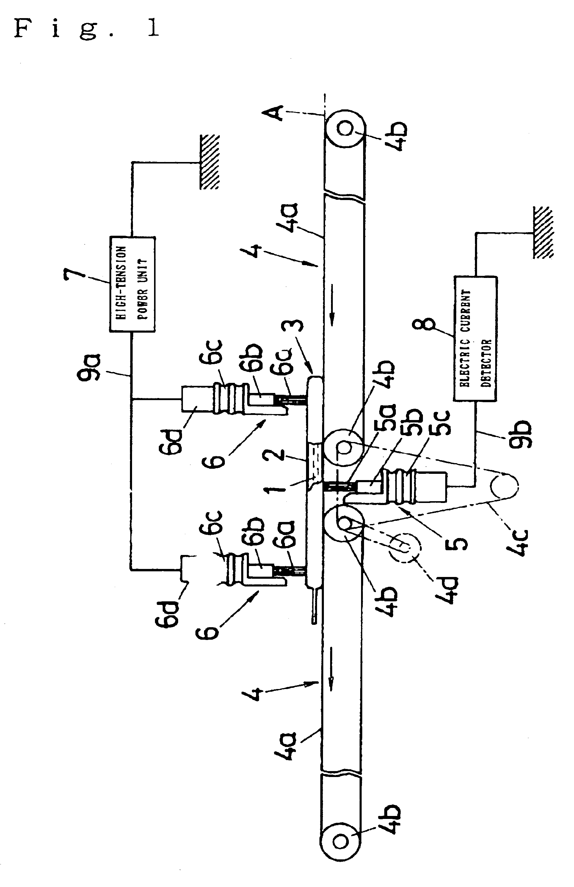
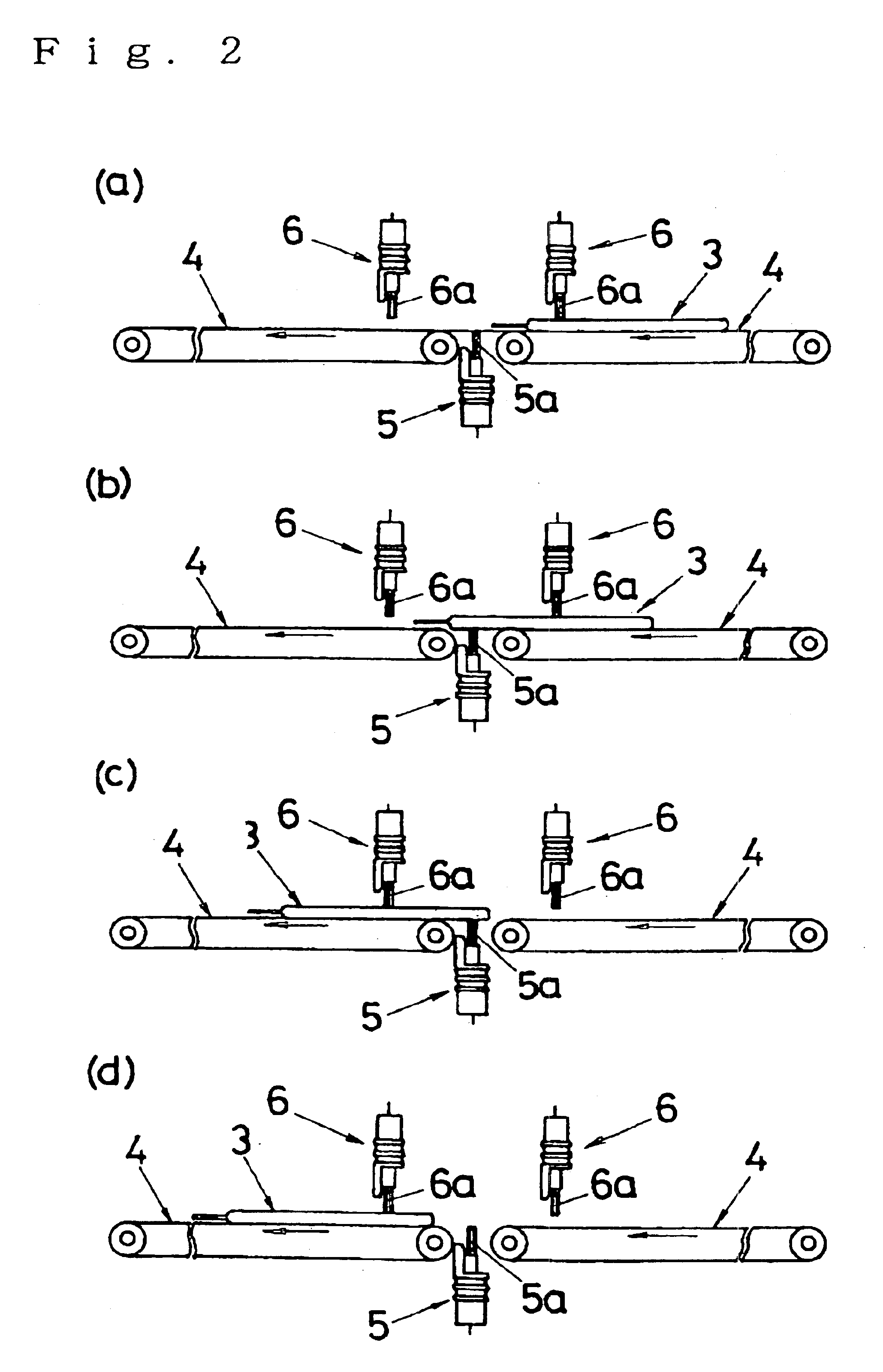
Using this device, the hermetically sealed package 3 can be conveyed by the operation of the two longitudinally conveyors 4, 4. From both sides of the path A, the conductive element 5 arranged on one side of the path A and at least one of the two longitudinally arranged conductive elements 6, 6 arranged on the other side, simultaneously contact the opposing surfaces of the contents 1--existing portion of the hermetically sealed package 3 that is moving on the path A. In this condition, a high voltage is applied to the hermetically sealed package 3 from the high-tension power unit 7. If a change in the electric current is detected by the electric current detector 8 at the portion where the conductive element 5 contacts and the portion where at least one of the two longitudinally arranged conductive elements 6, 6 contacts, it is concluded that at least one of the opposing surfaces of the contents 1--existing portion of the hermetically sealed package 3 has a pinhole. In this way, it is possible to inspect the entire areas of the opposing surfaces of the contents 1--existing portion of a hermetically sealed package 3 simultaneously from both surfaces to check whether or not there is a pinhole on any portion of at least one of the opposing surfaces.
If there is a pinhole on any portion of at least one of the opposing surfaces of the contents 1--existing portion of the hermetically sealed package 3 being conveyed, over the entire areas of the opposing surfaces, a change occurs in the electric current at the portion where the conductive element 5 contacts and the portion where at least one of the two longitudinally arranged conductive elements 6, 6 contacts. If the electric current detector 8 detects the change in the electric current, it is concluded that at least one of the opposing surfaces of the contents 1--existing portion of the hermetically sealed package 3 has a pinhole. In this way, it is possible to inspect the entire areas of the opposing surfaces of the contents 1--existing portion of a hermetically sealed package 3 simultaneously form both surfaces to check whether or not there is a pinhole on any portion of at least one of the opposing surfaces.
In the present invention, the longitudinal distance between the two conductive elements 6, 6, which are on the opposite side of the path A from the conductive element 5, can be extended generously within the range in which either one of them and the conductive element 5 can simultaneously touch the opposing surfaces of the contents 1--existing portion of the hermetically sealed package 3 being carried. Accordingly, the conductive element 6 and the conductive element 5 can be separated as far as possible. As a result, it is possible to make it difficult to produce sparks between the conductive element 6 and the conductive element 5, raising the limit to which the applicable voltage can be increased without causing any problem to inspections for pinholes.
The inspection method described in claim 1 has the following advantages: it makes it possible to check whether there is a pinhole on at least one of the opposing surfaces of the contents-existing portion of a hermetically sealed package in simultaneous inspections of both surfaces; and it also makes it possible to increase the voltage applied.
The inspection device of the present invention has the following effect: it is possible to convey relatively flat hermetically sealed packages one after another, and while doing so, inspect the entire areas of the opposing surfaces of the contents 1--existing portion of a hermetically sealed package 3 simultaneously from both surfaces to check continuously, accurately and without an error whether or not there is a pinhole on any portion of at least one of the opposing surfaces.
When the present invention is applied to such hermetically sealed packages having flat surfaces as described above, it is possible to have the conductive element 5 and one of the two longitudinally arranged conductive elements 6, 6 contact the opposing surfaces of the contents 1--existing portion of a hermetically sealed package 3 simultaneously. In this way, it is easily examined whether there is a pinhole on at least one of the opposing flat surfaces of the contents 1--existing portion in simultaneous inspections of both surfaces.

Problems solved by technology

A pinhole in the package of a medical consumable product causes contamination or decomposition of the contents.
A pinhole in the package of a food product causes the contents to contact the atmosphere, leading to decomposition or decay of the contents.
In this method, malfunctions are inevitable.
Moreover, when a high voltage is applied to the two electrodes holding a hermetically sealed package between them, an electric potential difference concentrates on the weak portion of the electric insulating film of the hermetically sealed package, providing a cause for pinholes.
As a result, there will be more pinholes, adversely affecting the subject.
In either method, while it is possible to check whether or not there are pinholes on the surface of the test portion of the hermetically sealed package that the supporting electrode contacts, it is impossible to check whether or not there are pinholes on the two, relatively wide, opposing surfaces of the hermetically sealed package in simultaneous inspections of the both surfaces.

Method used


Image

  • Device for inspecting hermetically sealed packages
  • Device for inspecting hermetically sealed packages
  • Device for inspecting hermetically sealed packages

Examples


Embodiment Construction

The drawings depict a case in which the hermetically sealed package 3 for inspection is a flat bag.

This bag 3 is made of a moderately thick plastic film 2 and has a cross section of approximately 130 mm (width).times.180 mm (length).times.12 m (height) and a volume of approximately 400 ml.

Each of the two longitudinally arranged conveyors 4, 4 for conveying this bag 3 consists of an endless belt 4a of a width slightly wider than 160 mm, which is capable of conveying the bag 3 in a stable manner. The belt 4a has a thickness of approximately 1 mm. The endless belt 4a is hung on a pair of longitudinally arranged rollers 4b, 4b each having a diameter of approximately 40 mm. In order to allow the conductive element 5 to approach from one side of the path A, the conveyors 4, 4 are set apart by approximately 35 mm.

In FIG. 1, in order to make,the two longitudinally arranged conveyors 4, 4 run in the same direction at the same speed, the rear roller 4b of the downstream conveyor 4 and the fro...


PUM

PropertyMeasurementUnit
volumeaaaaaaaaaa
widthaaaaaaaaaa
widthaaaaaaaaaa

Abstract

While a sealed package (3) prepared by wrapping conductive contents (1) with an electric-insulation film (2) is being conveyed by two conveyors (4, 4), front and rear, a conductor (5) disposed on one side of a conveyance path (A) and at least one of two conductors (6, 6), front and rear, disposed on the other side are simultaneously contacted with opposed surfaces of the sealed package (3) being conveyed. In this state, a high voltage from a high voltage source (7) is applied to the sealed package (3), and a current detector (8) is used to detect whether or not a change in current is occurring in the portion which is in contact with the conductor (5) and the portion which is in contact with at least one of the two conductors (6, 6) so as to find pinholes in the sealed package (3). Whether or not there is a pinhole in at least one of the opposed surfaces in the portion of the sealed package (3) where the contents (1) exist can be detected by simultaneous inspection from both surfaces. Pinhole inspection can be effected by increasing the applied voltage.

Description

The present invention relates to a method and a device for detecting pinholes on hermetically sealed packages, which wrap, with an electric insulating film, conductive contents, e.g, medical consumable products such as blood products and normal saline solutions, as well as foods, etc.Hermetically sealed packages are used in a variety of products today to maintain the sterilized condition of the contents of these products. These products include a number of products, for example, a variety of medical consumable products such as blood for transfusion and blood products, as well as food products such as retort foods.It is extremely important to inspect these hermetically sealed packages for pinholes. A pinhole in the package of a medical consumable product causes contamination or decomposition of the contents. A pinhole in the package of a food product causes the contents to contact the atmosphere, leading to decomposition or decay of the contents.In a conventional method for detecting...

Claims


Application Information

Patent Timeline
Patent Type & Authority Patents(United States)
IPC IPC(8): G01N27/20B65B57/00G01N27/92
CPCG01N27/205B65B57/02
Inventor YASUMOTO, KENJI
Owner JOVEN ELECTRIC
Learn More