
Reactor with remote plasma system and method of processing a semiconductor substrate

a plasma system and plasma technology, applied in the direction of chemical vapor deposition coating, solid-state diffusion coating, coating, etc., can solve the problems of instability in already deposited films, limit the application of devices,

Inactive Publication Date: 2004-08-31
KOKUSAI SEMICON EQUIP CORP
View PDF34 Cites 31 Cited by
  • Summary
  • Abstract
  • Description
  • Claims
  • Application Information

AI Technical Summary

Benefits of technology

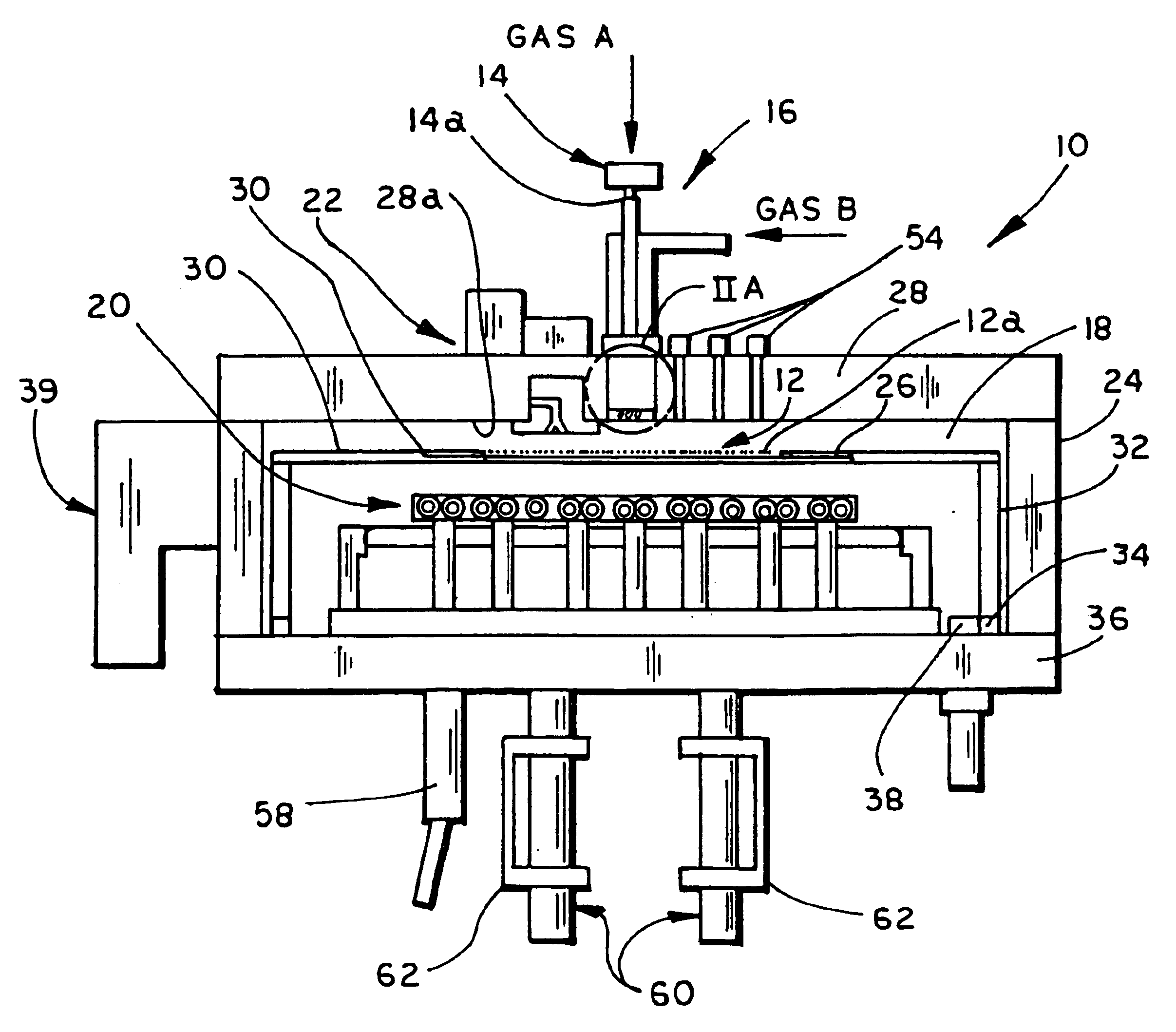
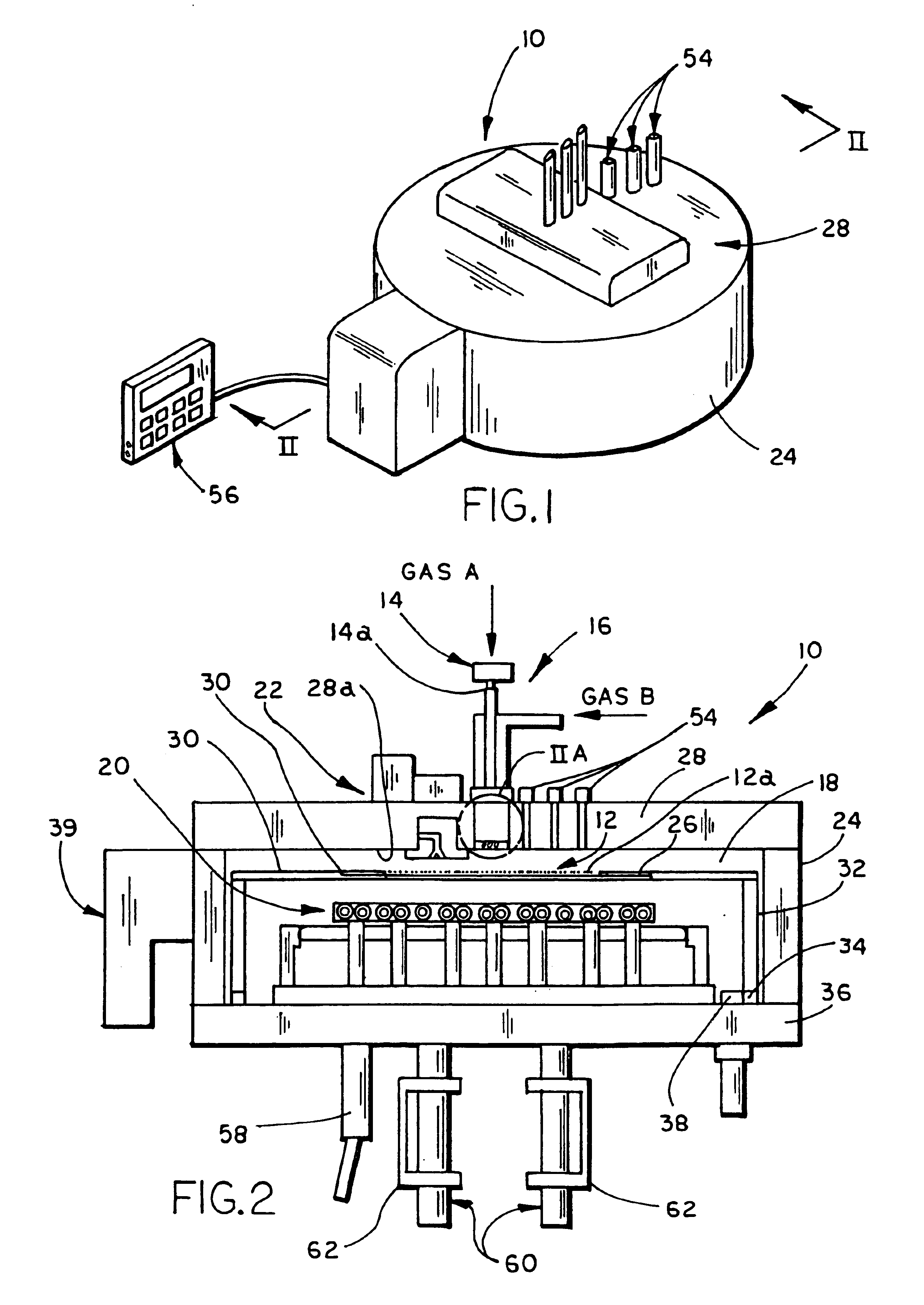
In one form of the invention, a reactor for processing a semiconductor substrate includes a reactor housing, which defines a processing chamber and is adapted to support a semiconductor substrate, and at least one gas injection assembly. The gas injection assembly injects at least one gas into the processing chamber and onto the substrate and is adapted to ionize the gas injected into the processing chamber to increase the reactivity of the gas with the substrate to thereby enhance the processing of the semiconductor substrate.

Problems solved by technology

However, the elevated temperatures associated with the thermal processing and chemical deposition processes sometimes limit the device application and, further, may cause instability in already deposited films.

Method used


Image

  • Reactor with remote plasma system and method of processing a semiconductor substrate
  • Reactor with remote plasma system and method of processing a semiconductor substrate
  • Reactor with remote plasma system and method of processing a semiconductor substrate

Examples


example 2

The film deposition rate of silane and ammonia at 400 mTorr and 750.degree. C. can be achieved at around 400.degree. C. if the reactant gases are ionized into a plasma.

example 3

When pure oxygen gas is injected at elevated temperatures of 900.degree. to 1,100.degree. C., a silicon wafer can be ionized into silicon dioxide. When oxygen plasma is injected into reactor 10, silicon dioxide can be formed at the surface of a silicon wafer at temperatures as low as room temperature. Alternately, higher growth rates can be achieved when oxygen plasma is injected into chamber 18 onto a silicon wafer at or near 400.degree. C., which is well below the 1,100.degree. C. thermal processing conditions associated with non-ionized oxygen.

In addition to reducing the temperature requirements for film deposition, by injecting reactant gases in plasma form, already formed devices will not be exposed to the higher temperatures associated with the further film depositions and, therefore, will remain stable. Further, the injection of gases in plasma form enables new device applications, for example:

example 4

Nitrogen gas does not react with a bare silicon wafer even when injected at temperatures of 1,150.degree. C. When nitrogen is injected in plasma form into chamber 18 onto a silicon wafer, a very thin film of silicon nitride is formed at room temperature. This deposition reaction is even further enhanced when the nitrogen is ionized using a helium plasma.


PUM

PropertyMeasurementUnit
Diameteraaaaaaaaaa
Reactivityaaaaaaaaaa
Semiconductor propertiesaaaaaaaaaa

Abstract

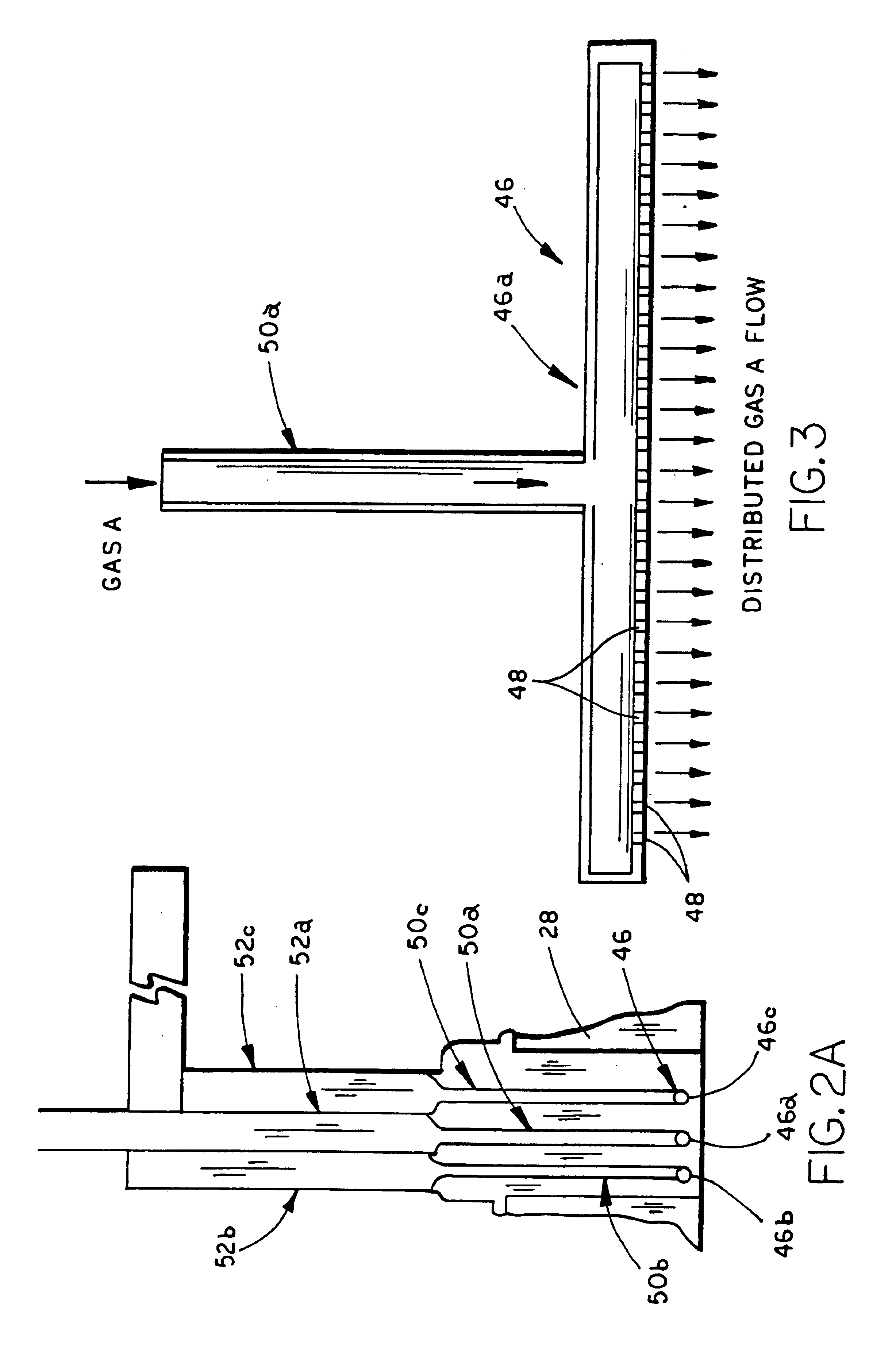
A reactor for processing a semiconductor substrate includes a reactor housing which defines a processing chamber, and at least one gas injecting assembly. The processing chamber is adapted to support a semiconductor substrate therein. The gas injection assembly injects at least one gas into the processing chamber and onto the substrate and is adapted to ionize the gas injection into the processing chamber to increase the reactivity of the gas with the substrate to thereby enhance the processing of the semiconductor substrate. In preferred form, the gas is ionized into a gas plasma. For example, the gas injection assembly may include a gas plasma generator which ionizes the gas with an electromagnetic field. Preferably, the gas plasma generator ionizes the gas exteriorly of the processing chamber to isolate the substrate from the plasma generator. The gas injection assembly further includes one or more injection tubes, preferably quartz tubes, with each tube including a plurality of orifices through which the ionized gas is delivered into the processing chamber.

Description

BACKGROUND AND TECHNICAL FIELD OF THE INVENTIONThe present invention relates to a processing reactor and, more particularly, to a processing reactor for the thermal processing and chemical deposition of thin film applications on a substrate, such as a semiconductor wafer, in which chemical reactants are excited prior to injection into the reactor's processing chamber to provide better control of the substrate processing conditions and, further, to enable new semiconductor device applications.Several processing steps of semiconductor substrates involve chemical reactions at elevated temperatures. Heretofore, control of the deposition and annealing processes has been achieved by controlling the gas flow and pressure and, further, the wafer temperature. Various methods have been developed for measuring the temperature of a substrate during processing in order to improve the control of the various processes. For example, commonly assigned U.S. Pat. No. 5,814,365 discloses an improved re...

Claims


Application Information

Patent Timeline
IPC IPC(8): C23C8/36C23C16/44C23C8/06C23C16/448C23C16/452C23C16/455H01L21/205H01L21/302H01L21/3065H01L21/31H01L21/316H01L21/318
CPCC23C8/36C23C16/4405C23C16/452C23C16/45576C23C16/45578
Inventor MAHAWILI, IMAD
Owner KOKUSAI SEMICON EQUIP CORP
Learn More