
Method of and system for flushing one or more cells in a particle-based electrochemical power source in standby mode

a technology of electrochemical power source and particle-based electrochemical, which is applied in the direction of separation process, basic electric element, electric apparatus, etc., can solve the problems of particle buildup, recirculation and electrochemical reaction can have undesired consequences, and reduce the flow of reaction solution through the anode bed

Inactive Publication Date: 2004-07-20
METALLIC POWER INC
View PDF109 Cites 13 Cited by
  • Summary
  • Abstract
  • Description
  • Claims
  • Application Information

AI Technical Summary

Benefits of technology

"The invention provides a method and system for flushing cells in a particle-based electrochemical power source that is in standby mode of operation. The method involves delivering and withdrawing reaction solution to and from the cells, which helps to keep the cells clean and efficient. The flushing process can help to prevent clogging, buildup, and precipitation of solid reaction products that can reduce the flow of reaction solution throughout the cell. The invention can improve the efficiency and lifespan of particle-based electrochemical power sources."

Problems solved by technology

Particle-based electrochemical power sources, including without limitation metal-based fuel cells, which employ particulate anodes and which deliver reaction agents such as hydroxides to the anodes through a reaction solution pose particular challenges since, for such power sources (e.g., fuel cells) to function efficiently, it is appropriate to re-circulate the reaction solution throughout and within the particulate anodes so that the appropriate electrochemical reaction can take place.
However, this recirculation and electrochemical reaction can have undesired consequences.
These unintended consequences include certain problems of particle buildup, reduction in reaction solution flow through anode bed (e.g., clogging), and precipitation of solid zinc oxide that can occur during either the discharge cycle mode of operation due to the electrochemical reaction or the standby mode of operation due to the corrosion reaction described above.
The dense packing of the small particles can lead to particle buildup, clogging and interference with, and resulting reduction of, the flow of reaction solution throughout and within the particulate anodes.
This in turn can lead to the generation of insoluble reaction products, which can further reduce the flow of reaction solution throughout the cell and / or the reaction bed.
The result is typically a substantially less efficient fuel cell.
A related problem is that, as electrochemical dissolution occurs, the concentration of reaction products can increase.
Even when the fuel cell is in a standby mode, and is not undergoing electrochemical dissolution, these problems can occur through a corrosion reaction that occurs.
Consequently, as this reaction occurs, zincate will build up, and when the zincate saturation level is reached, solid zinc oxide can precipitate out and clog the anode beds as described above.
Moreover, because zinc is consumed in this reaction, this reaction will also result in smaller zinc particles, which can also lead to clogging of the anode beds as described above.

Method used


Image

  • Method of and system for flushing one or more cells in a particle-based electrochemical power source in standby mode
  • Method of and system for flushing one or more cells in a particle-based electrochemical power source in standby mode
  • Method of and system for flushing one or more cells in a particle-based electrochemical power source in standby mode

Examples


example

FIG. 7 is a front view of an embodiment of an individual cell 700 within the power source 102 of a metal-based fuel cell. A particulate anode 708 is maintained within a cell cavity 704 of the cell. Within the cell cavity 704, when the cell is in standby mode, the particulate anode may undergo electrochemical dissolution (although at a much slower rate than the discharge mode) due to corrosion.

A first flow path for a recirculating flow of the reaction solution is provided through the anode. This flow path may be activated in the standby mode of operation. In the particular embodiment illustrated in FIG. 7, the first flow path extends from top to bottom through the anode, and is represented by the vertical arrows within cell cavity 704. When the power source is in the standby mode, reaction solution (usually essentially free of metal particles, although it is possible to include them) enters the cell at orifice 714, proceeds along conduit 716, and is distributed into the cell by flow ...

second embodiment

cell 700 is illustrated in FIG. 9. This embodiment is identical to the embodiment illustrated in FIG. 7, except that flow distributor 706 here includes a plurality 722 of fluid mechanical devices for allowing at least a portion of the reaction solution (and optionally particulate material) flowing along flow path 720 to enter the cell cavity, with the remainder exiting the cell cavity through orifice 724. As explained in U.S. Pat. No. 6,296,958, which is hereby fully incorporated herein by reference, the fluid mechanical devices should be configured in such a way that vortices are created in the spaces between adjacent ones of the fluid mechanical devices. These vortices draw reaction solution and optionally particulate material flowing along flow path 722 in a substantially uniform manner.


PUM

PropertyMeasurementUnit
flow rateaaaaaaaaaa
electrochemical potentialaaaaaaaaaa
pressureaaaaaaaaaa

Abstract

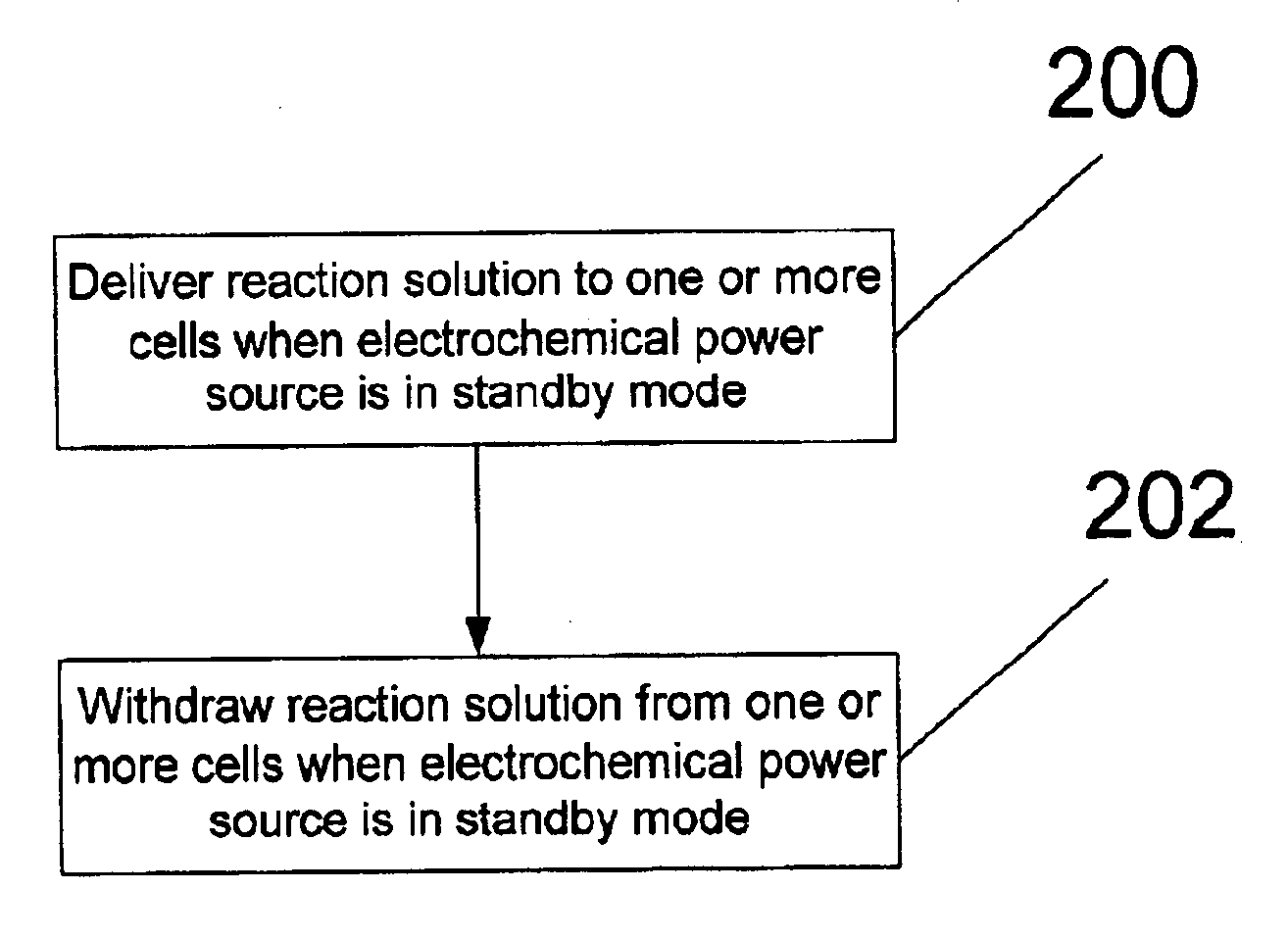
A method of and system for flushing one or more cells or components thereof in a particle-based electrochemical power source is provided. Reaction solution is delivered to and withdrawn from the one or more cells when the electrochemical power source is in a standby mode of operation.

Description

This invention relates generally to the field of particle-based electrochemical power sources, and, more specifically, to techniques for flushing the cells thereofRELATED ARTParticle-based electrochemical power sources, including without limitation metal-based fuel cells, are emerging as an attractive alternative to traditional energy sources. In metal-based fuel cells, when metal anodes within the cell cavities are exposed to an electrolysis agent such as hydroxide, an electrochemical reaction takes place whereby the metal releases electrons, and a reaction product is formed, typically one or more ions or oxides of the metal. Through this process, the metal anodes are gradually consumed. The released electrons flow through a load to a cathode, where they react with a second reactant such as oxygen.Particle-based electrochemical power sources, including without limitation metal-based fuel cells, which employ particulate anodes and which deliver reaction agents such as hydroxides to ...

Claims


Application Information

Patent Timeline
Patent Type & Authority Patents(United States)
IPC IPC(8): H01M12/06H01M12/00H01M8/22H01M4/02H01M8/04
CPCH01M8/225H01M12/065H01M4/02H01M8/04223H01M2004/024Y02E60/50H01M8/04186H01M8/04753H01M8/241H01M8/0258H01M8/04225
Inventor SMEDLEY, STUART I.NOVKOV, DONALD JAMESSMEDLEY, KENT I.ALSTADT, RAYMOND H.GROCHULSKI, FREDERICK R.
Owner METALLIC POWER INC
Learn More