
Tufted surface covering and method

a surface covering and tufted technology, applied in the field of improved tufted surface covering and method, can solve the problems of damage to the covering, dispersion of force affecting the traction and torque characteristics of the covering, and not functionally equivalen

Inactive Publication Date: 2004-04-20
WALTERS IAN D
View PDF18 Cites 80 Cited by
  • Summary
  • Abstract
  • Description
  • Claims
  • Application Information

AI Technical Summary

Benefits of technology

The solution provides a surface that absorbs impacts similarly to natural turf, resisting wear, water, and environmental factors, while maintaining traction and torque characteristics, and allowing multidirectional movement.

Problems solved by technology

Entry of moisture into the needle holes surrounding the tufts, followed by repeated freeze-thaw cycles, would eventually damage the covering.
This dissipation of force affects the traction and torque characteristics of the covering.
For this reason, although known synthetic turf surfaces may be constructed to visually resemble natural grass turf, they are not functionally equivalent.
There are also certain weaknesses of dimensional stability associated with surface coverings constructed by laminating multiple layers.
In addition, known artificial turf surfaces demonstrate limited ability to withstand the heavy wear and substantial stresses associated with high impact sports over extended periods of time.
Because such laminated sport surfaces do not provide significant horizontal movement, these tangential forces can cause the turf to delaminate with wear.
In the case of laminated golf mats, lack of horizontal elasticity may actually cause the carpet layer to melt to the club upon striking.

Method used


Image

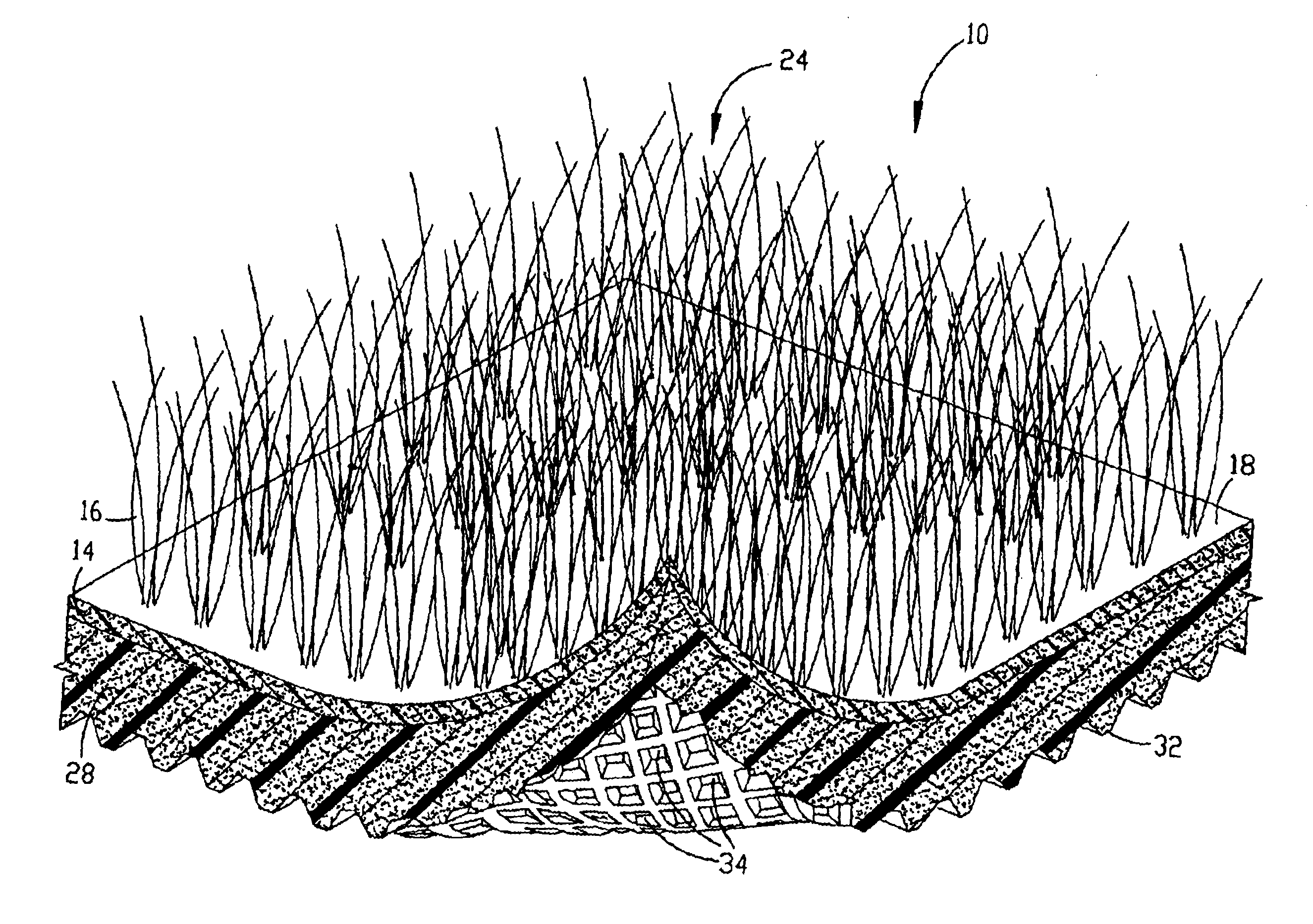
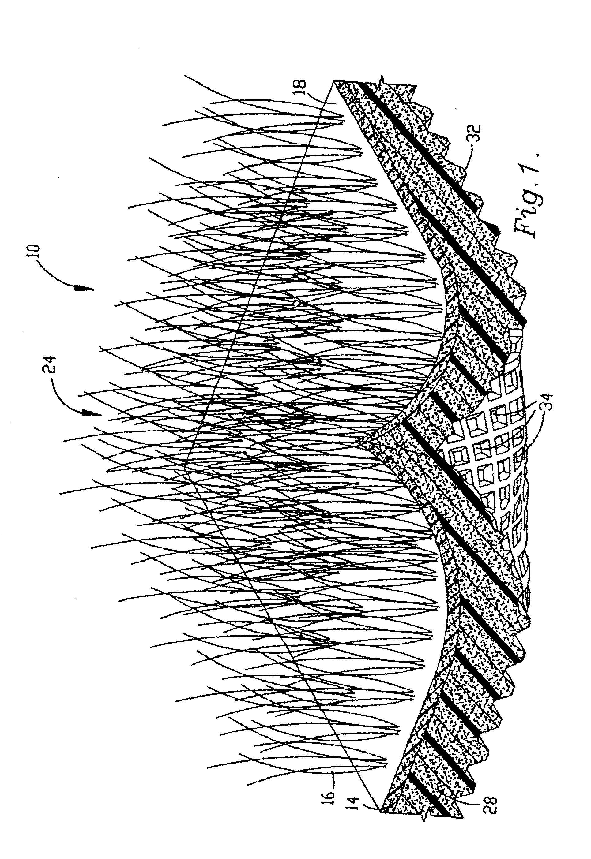
  • Tufted surface covering and method
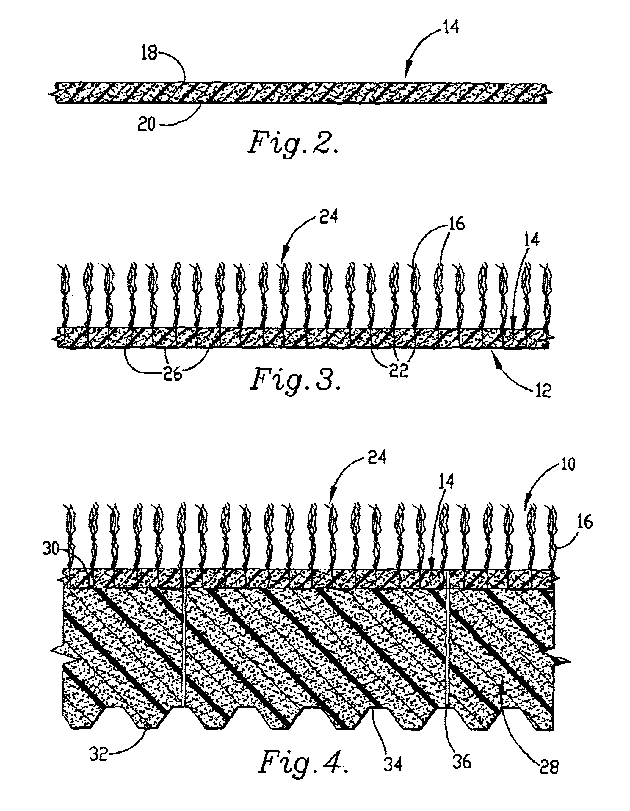
  • Tufted surface covering and method
  • Tufted surface covering and method

Examples


Embodiment Construction

A golf practice mat having a tufted first layer and a second layer is prepared as follows:

A First Batch Mix is prepared by mixing:

9.0 parts by weight mixed recycled particles of NBR, SBR and EPDM

1.0 part by weight mixed PVC and EPDM

0.5 parts by weight diisononyl phthalate

0.2 parts by weight trinonylphenolphosphate

0.175 parts by weight talc

0.12 parts by weight tinuvin

A slurry is prepared by mixing:

10.0 parts by weight First Batch Mix

0.125 parts by weight sulfur

0.1 part by weight stearic acid

4.0 parts by weight carbon

0.05 parts by weight diisononyl phthalate

0.5 parts by weight zinc oxide

2.5 parts by weight azodicarbonamide

The slurry is poured into a 20 mm deep form and passed through a press at 160.degree. C. and 1.5 tons per square inch pressure to form a first layer.

The cured first layer is needle tufted on a tufting machine with a polyamide yarn fiber manufactured by Dupont under the trademark Antron.RTM..

The tufted mat is placed face down in a roller press heated to 160.degree. C....


PUM

PropertyMeasurementUnit
temperatureaaaaaaaaaa
particle sizeaaaaaaaaaa
sizesaaaaaaaaaa

Abstract

The tufted surface covering includes a base formed from particles of a thermosetting polymer compound mixed with a particle binding agent causing a portion of the particles to bind together to form a self supporting web. The base is tufted with a tufting material. Thermosetting vulcanized natural and / or synthetic rubber compounds are employed. The polymer layer is tufted with a tufting material and heated to a temperature of from about 110° C. to about 220° C. at an elevated pressure of up to two tons per square inch, to cause the particles to bind together at elevated temperature and pressure to anchor and seal the tufts in place. Cross-linking agents and polar polymer containing compounds may be employed as particle binding agents. In another aspect of the invention, a second layer of particles of a thermosetting polymer mixed with a particle binding agent may be joined together with the particles of the first layer at elevated temperature and pressure. A series of spaced apertures extends through the first and second layers to enable free draining of the surface covering. The lower surface of the covering includes spaced indentations to reduce the weight of the covering.

Description

BACKGROUND OF INVENTIONThe present invention relates to an improved tufted surface covering and method.Tufted surface coverings are employed indoors as floor coverings in the form of carpeting, area rugs, floor, gym, barrier and crash mats, as well as outdoors, in the form of carpeting, artificial turf, cushioned sport and play surfaces and sport mats. Surface coverings for sporting use are generally constructed by stitching into a preformed fabric backing layer to form tufts, and then bonding the primary backing layer to an impact-absorbing resilient lower layer or shock pad, by means of a thin, laminating layer.Conventional tufting machines employ rows of needles, which are threaded with a suitable yarn fed from a ball or creel through an aperture adjacent the tip of each needle. The tufting machine forces the rows of needles through a backing fabric. The needles pierce the fabric from back to front, pushing the yarn through the backing. Looping tools catch the yarn loops on the f...

Claims


Application Information

Patent Timeline
Patent Type & Authority Patents(United States)
IPC IPC(8): D06N7/00
CPCD06N7/0084D06N2209/1692D06N2203/065D06N2203/045D06N2203/042D06N2209/1685D06N2201/0263D06N2201/02D06N2205/04D06N2203/048D06N2203/068D06N2205/20D06N2209/101D06N2205/023D06N2203/047D06N2203/02D06N2203/022D06N2201/0254Y10T428/23921Y10T428/23979Y10T428/23986
Inventor WALTERS, IAN D.
Owner WALTERS IAN D
Learn More