
Method of thermal NOx reduction in catalytic combustion systems

a technology of catalytic combustion and thermal nox reduction, which is applied in the ignition of turbine/propulsion engines, engine starters, lighting and heating apparatus, etc., can solve the problems of increasing difficulty in finding the window of low nox and acceptable co

Inactive Publication Date: 2004-04-13
KAWASAKI HEAVY IND LTD
View PDF68 Cites 49 Cited by
  • Summary
  • Abstract
  • Description
  • Claims
  • Application Information

AI Technical Summary

Benefits of technology

The invention is about controlling the production of nitrogen oxides (NOx) in gas turbine systems by reducing the time that the gas mixture is at high temperatures. This is achieved by adjusting the catalyst outlet temperature, which changes the position of the homogeneous combustion wave. By controlling the catalyst outlet temperature, the time period during which the flame produces thermal NOx can be minimized, while maintaining acceptable levels of carbon monoxide (CO) and other emissions. The invention is useful in combustor systems using the partial downstream combustion technology.

Problems solved by technology

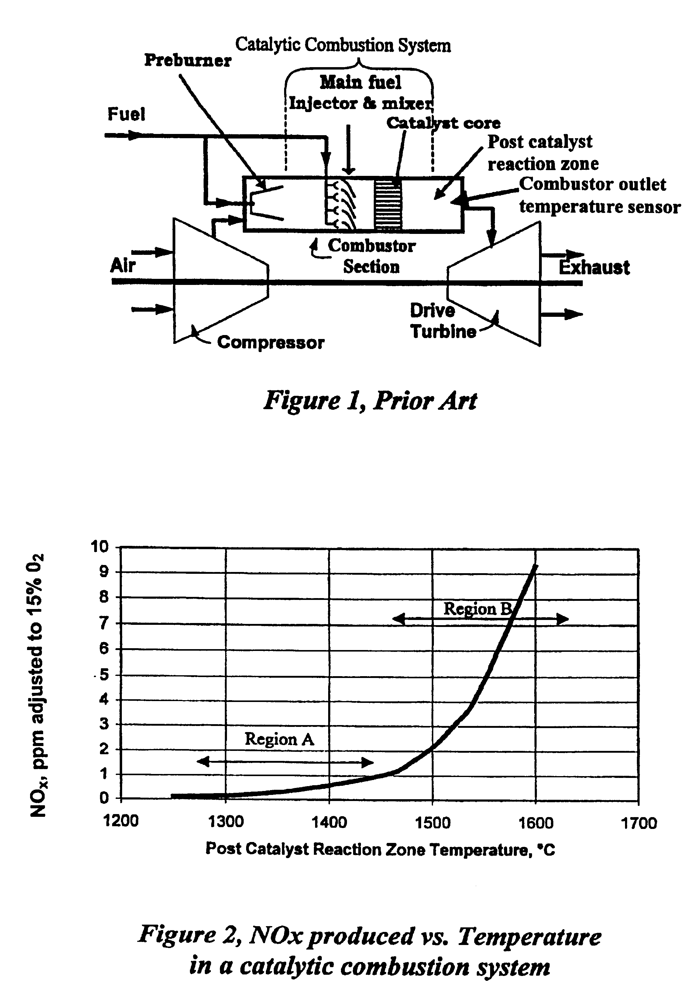
However, to meet ever more stringent emissions standards, turbine operating conditions must be controlled so that the amount of NOx produced does not increase.
There is a similar problem with CO in the combustor output gases, in that regulations currently require less than about 100 ppm, and the movement is toward 10 ppm or less.
Thus, finding the window of low NOx and acceptable CO is increasingly difficult at the high FIG. 2, Region B, temperatures needed for efficient energy extraction.

Method used


Image

  • Method of thermal NOx reduction in catalytic combustion systems
  • Method of thermal NOx reduction in catalytic combustion systems
  • Method of thermal NOx reduction in catalytic combustion systems

Examples


Embodiment Construction

The following detailed description illustrates the invention by way of example, not by way of limitation of the principles of the invention. This description will clearly enable one skilled in the art to make and use the invention, and describes several embodiments, adaptations, variations, alternatives, and uses of the invention, including what are presently believed to be the best modes of carrying out the invention.

In this regard, the invention is illustrated in the several figures and tables, and is of sufficient complexity that the many parts, interrelationships, process steps, and sub-combinations thereof simply cannot be fully illustrated in a single patent-type drawing or table. For clarity and conciseness, several of the drawings show in schematic, or omit, parts or steps that are not essential in that drawing to a description of a particular feature, aspect or principle of the invention being disclosed. Thus, the best mode embodiment of one feature may be shown in one draw...


PUM


Abstract

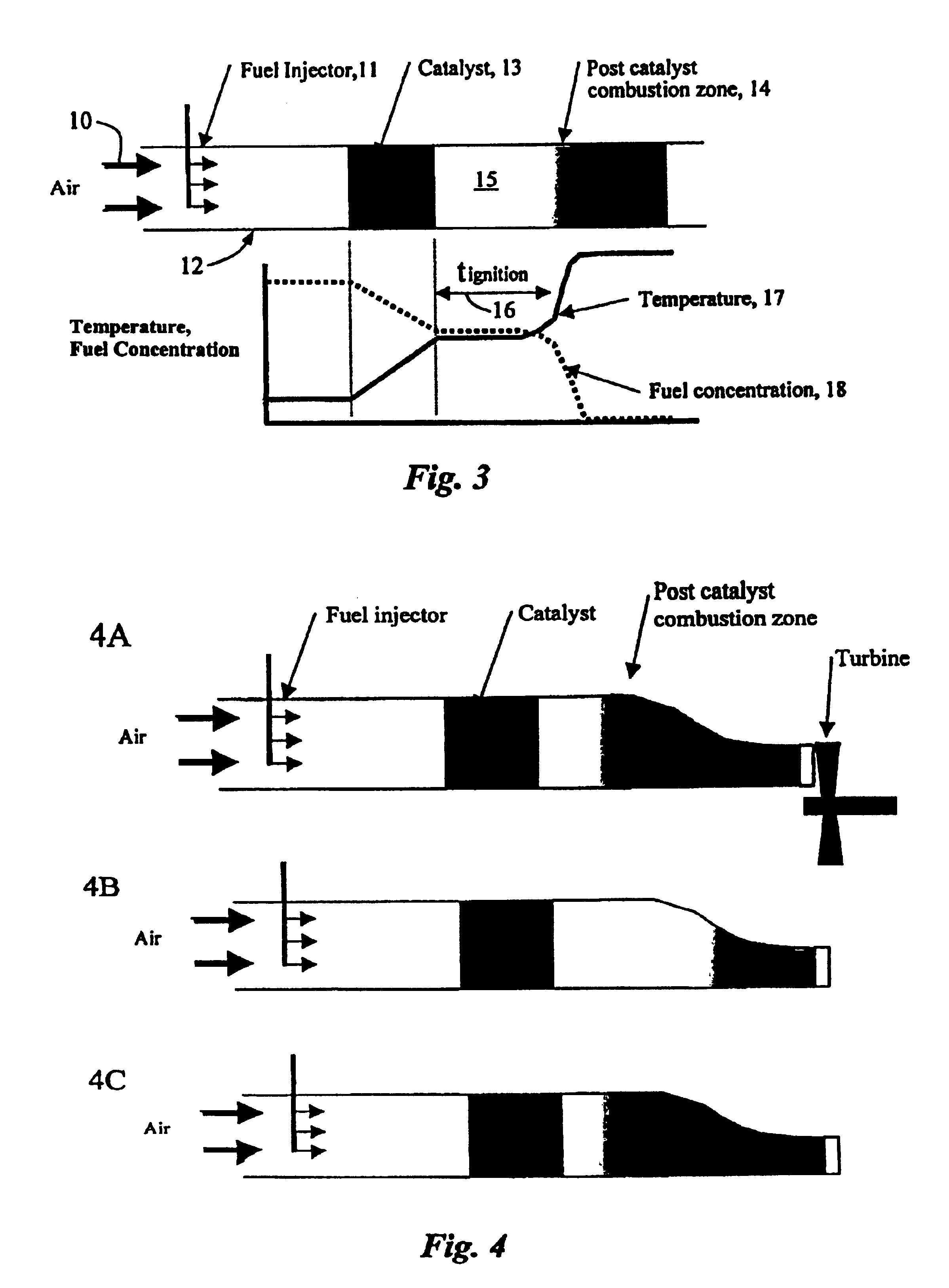
Methods and apparatus, both devices and systems, for control of Zeldovich (thermal) NOx production in catalytic combustion systems during combustion of liquid or gaseous fuels in the post catalytic sections of gas turbines by reducing combustion residence time in the HC zone through control of the HC Wave, principally by adjusting the catalyst inlet temperature. As the fuel / air mixture inlet temperature (to the catalyst) is reduced, the HC Wave moves downstream (longer ignition delay time), shortens the residence time at high temperature, thereby reducing thermal NOx production. The countervailing increase in CO production by longer ignition delay times can be limited by selectively locating the HC Wave so that thermal NOx is reduced while power output and low CO production is maintained. NOx is reduced to on the order of <3 ppm, and preferably <2 ppm, while CO is maintained <100 ppm, typically <50 ppm, and preferably <5-10 ppm.

Description

The invention relates to methods and apparatus, both devices and systems, for control of NOx in catalytic combustion systems, and more particularly the control of NOx produced downstream of the catalytic reaction zone of a combustor, while at the same time maintaining the same power output yet low CO, by reducing combustion residence time, inter alia, through control of the location of the homogeneous combustion wave.Gas turbines are used for a variety of purposes, among them: motive power; gas compression; and generation of electricity. The use of gas turbines for electrical generation is of particular and growing interest due to a number of factors, among them being modularity of design, generation output capacity to size and weight, portability, scalability, and efficiency. In addition, gas turbines generally use low sulfur hydrocarbon fuels, principally natural gas, which offers the promise of lower sulfur oxides or SOx pollutant output. This is particularly important in urban a...

Claims


Application Information

Patent Timeline
Patent Type & Authority Patents(United States)
IPC IPC(8): F23R3/40F23R3/00
CPCF23R3/40
Inventor DALLA BETTA, RALPH A.VELASCO, MARCO A.YEE, DAVID K.NICKOLAS, SARENTO G.
Owner KAWASAKI HEAVY IND LTD
Learn More