
Electronic circuit, semiconductor device, electronic equipment, and timepiece

a technology of electronic equipment and timepieces, applied in the field of electronic circuits, semiconductor devices, electronic equipment, and timepieces, can solve problems such as errors in time display, inability to accurately record time, and constant voltage output from constant voltage generation circuits that vary with the effects of temperatur

Inactive Publication Date: 2004-02-03
SEIKO EPSON CORP
View PDF19 Cites 18 Cited by
  • Summary
  • Abstract
  • Description
  • Claims
  • Application Information

AI Technical Summary

Benefits of technology

This configuration maintains a stable constant voltage output, ensuring accurate timekeeping and reduced power consumption by finely adjusting the drive voltage to match the oscillation-stopped voltage of the crystal oscillation circuit, even under temperature changes.

Problems solved by technology

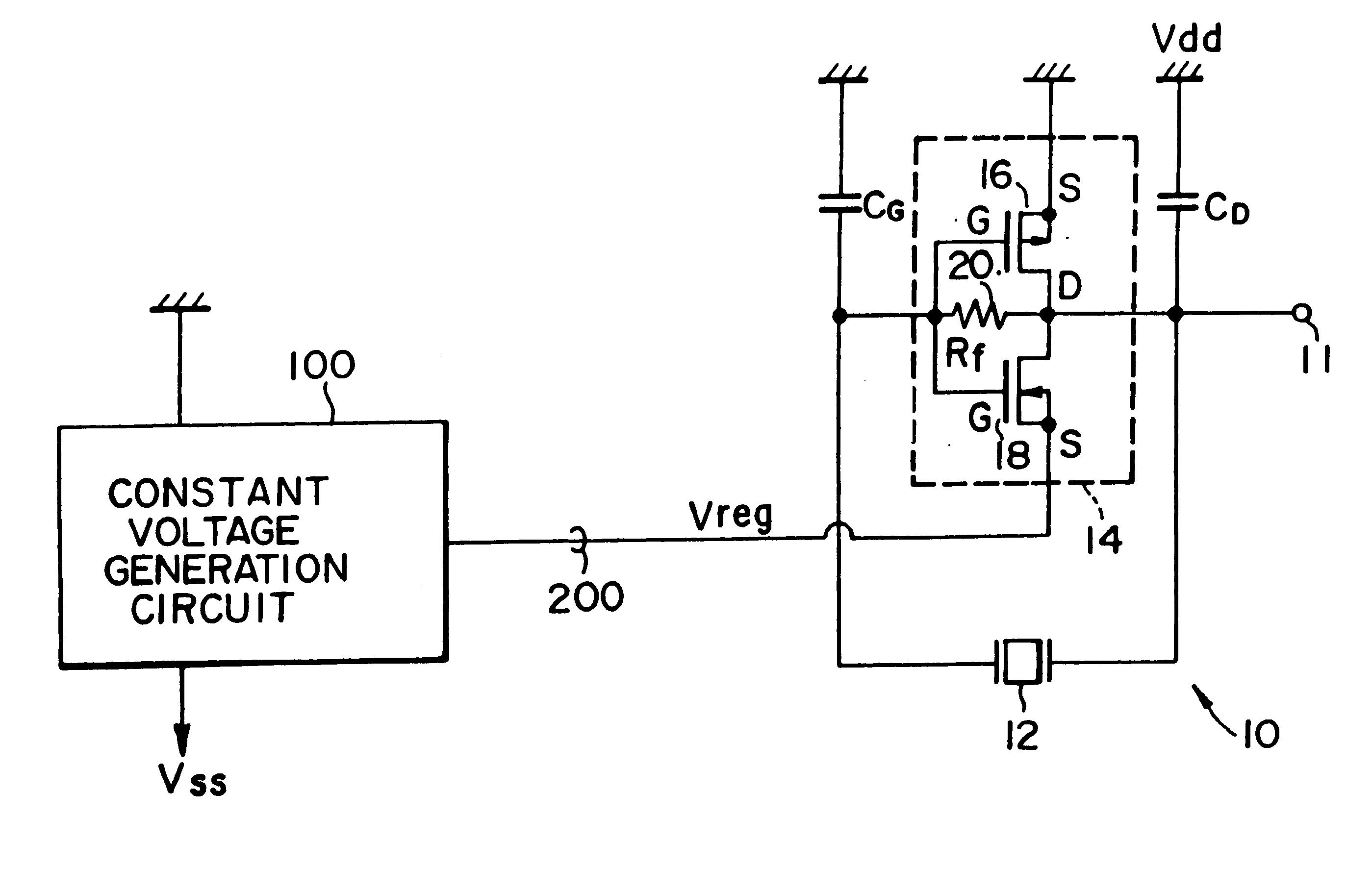
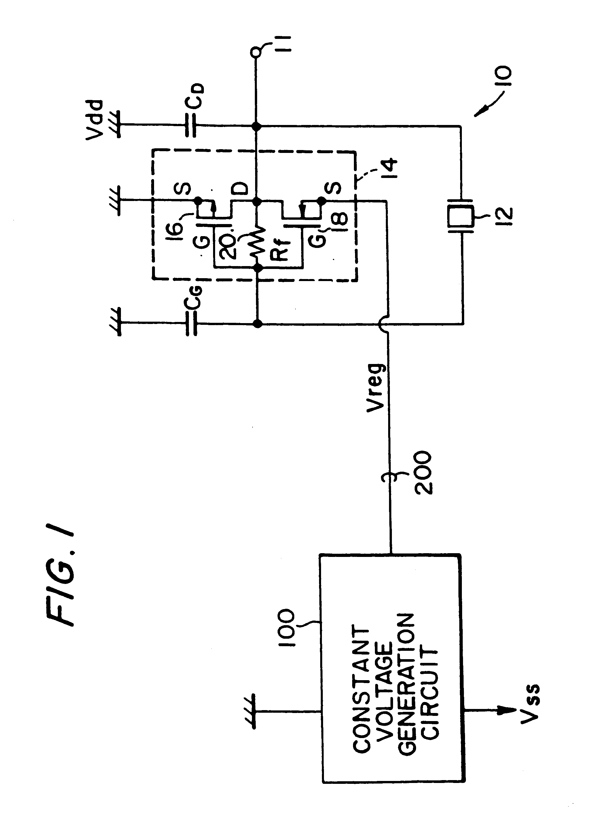
However, electronic circuitry formed as an IC has a problem in that a constant voltage that is output from the constant-voltage generation circuit varies with the effects of temperature.
This causes a problem in an electronic circuit that generates a reference clock signal for operation based on the oscillation frequency of this crystal oscillation circuit, in that accurate time-keeping is not possible.
If prior-art electronic circuitry is used in such a wristwatch, therefore, variations in the constant voltage that is output from the constant-voltage generation circuit can cause errors in the time displayed thereby.
If this voltage falls below the oscillation-stopped voltage, the crystal oscillation circuit will no longer be able to operate.
Since it is not possible to finely adjust the value of the constant voltage that is output from the constant-voltage generation circuit in prior-art electronic circuitry, it is necessary to set the value of this constant voltage to have a sufficiently large margin over the expected value of the oscillation-stopped voltage, from consideration of the risk of a large variation therein.
This means that the crystal oscillation circuit is driven by a voltage that is larger than necessary, raising a problem in that it is difficult to reduce the power consumption of the electronic circuitry from this aspect too.
As a result, a problem arises in that the crystal oscillation circuit 10 consumes power in a wasteful manner.

Method used


Image

  • Electronic circuit, semiconductor device, electronic equipment, and timepiece
  • Electronic circuit, semiconductor device, electronic equipment, and timepiece
  • Electronic circuit, semiconductor device, electronic equipment, and timepiece

Examples


Embodiment Construction

An example of the electronic circuitry used in a wristwatch to which this invention is applied is shown in FIG. 14.

This wristwatch has an internal electrical power generating mechanism (not shown in the figure). When the user moves the arm on which the wristwatch is worn, an oscillating weight of the electrical power generating mechanism rotates, a power-generation rotor is rotated at high speed by this kinetic energy, and an AC voltage is output from a power-generation coil 400 provided on a power-generation stator side thereof.

This AC voltage is rectified by a diode 404 and charges a secondary battery 402. This secondary battery 402 configures a main power source, together with a booster circuit 406 and an auxiliary capacitor 408.

When the voltage of the secondary battery 402 is too low to act as the drive voltage for the timepiece, the voltage of the secondary battery 402 is converted by the booster circuit 406 to a voltage high enough to drive the timepiece, and is stored in the ...


PUM


Abstract

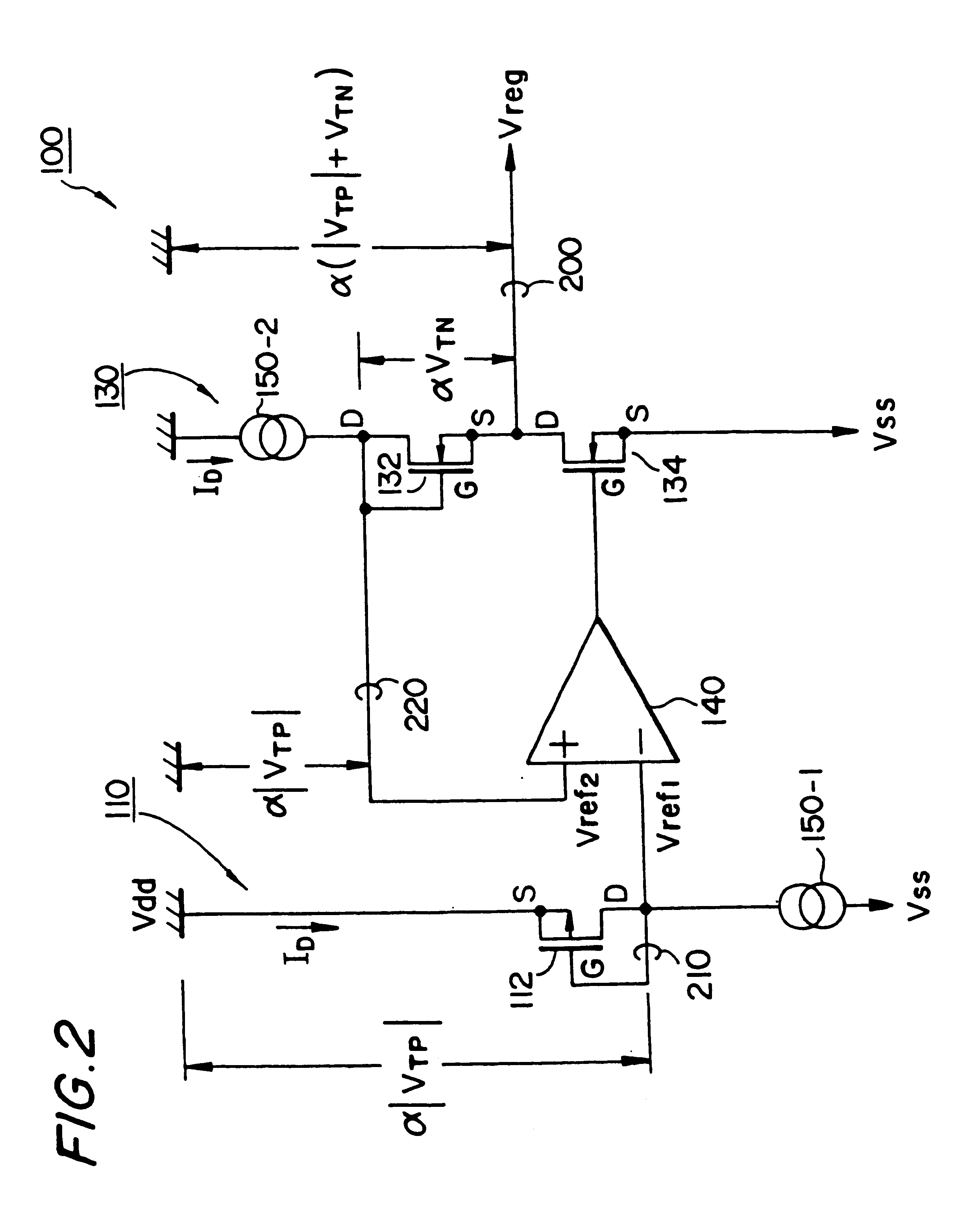
A constant-voltage generation circuit 100 creates a constant voltage. This constant-voltage generation circuit 100 comprises a first voltage creation circuit 110 for creating a reference voltage and a second voltage creation circuit 130 for creating the constant voltage which has a predetermined relationship with the reference voltage. The first voltage creation circuit 110 comprises a first constant-current source 150-1 for supplying a constant current and a first voltage-control transistor 112, through which this constant current flows, for outputting the reference voltage on the basis of a predetermined potential. The constant current is set to a value within the saturated operating region of the first voltage control transistor 112.

Description

1. Field of InventionThis invention relates to an electronic circuit, a semiconductor device, electronic equipment, and a timepiece.2. Description of Related ArtAn electronic circuit that is known in the art comprises a constant-voltage generation circuit that outputs a constant voltage and a crystal oscillation circuit that is driven by this constant voltage. This kind of electronic circuit is widely used in applications such as timepieces, telephones, and computer terminals.Recent trends in the miniaturization of electronic equipment have made it particularly common to fabricate such electronic circuitry as compact, low-power ICs.However, electronic circuitry formed as an IC has a problem in that a constant voltage that is output from the constant-voltage generation circuit varies with the effects of temperature.This is particularly important with a crystal oscillation circuit that is driven by a constant voltage output by a constant-voltage generation circuit because, if that con...

Claims


Application Information

Patent Timeline
Patent Type & Authority Patents(United States)
IPC IPC(8): G05F1/10G05F1/46G04G19/00G05F1/618G05F1/56G05F3/24G05F3/08
CPCG04G19/00G05F1/468G05F1/56G05F1/618G05F3/242
Inventor NAKAMIYA, SHINJIKADOWAKI, TADAOMAKIUCHI, YOSHIKI
Owner SEIKO EPSON CORP
Learn More