
Manifold for fuel cell system

a fuel cell and manifold technology, applied in the field of manifolds for fuel cells, can solve the problems of inapplicability to metal/air fuel cells, inability to achieve complexity, and undesirable variations in fluid concentration and/or flow ra

Inactive Publication Date: 2004-01-20
METALLIC POWER INC
View PDF115 Cites 15 Cited by
  • Summary
  • Abstract
  • Description
  • Claims
  • Application Information

AI Technical Summary

Benefits of technology

In a further aspect, the invention pertains to use of invention methods in suitable systems. Exemplary suitable systems include without limitation fuel cell subsystems, fuel cells, internal combustion engines, and the like, and suitable combinations of any two or more thereof. In any such system, the invention assists in the uniform delivery of each of the components of a single flow of a single or multiphase fluid to a plurality of destinations to which uniform delivery of at least one of the components is desired.

Problems solved by technology

However, one skilled in the art will readily recognize the geometric complexity that this technique introduces into the system after the second stage.
Such complexity is not practical for use in a metal / air fuel cell, which requires a more compact arrangement of parallel flow paths in order to integrate the manifold within a portable stacked cell design.
Multiphase fluid flow through such a manifold will typically produce undesirable variations in the fluid concentration and / or flow rate of the dispersed phase of the multiphase fluid.
The differences in pressure drops can cause differences in flow rates (e.g., velocities), and thus can result in differences in the flow rates of the dispersed phase.
Further, these differences in flow rates can result in different drag forces, and thus can result in different concentrations of the dispersed phase.

Method used


Image

  • Manifold for fuel cell system
  • Manifold for fuel cell system
  • Manifold for fuel cell system

Examples


Embodiment Construction

Making of a Manifold

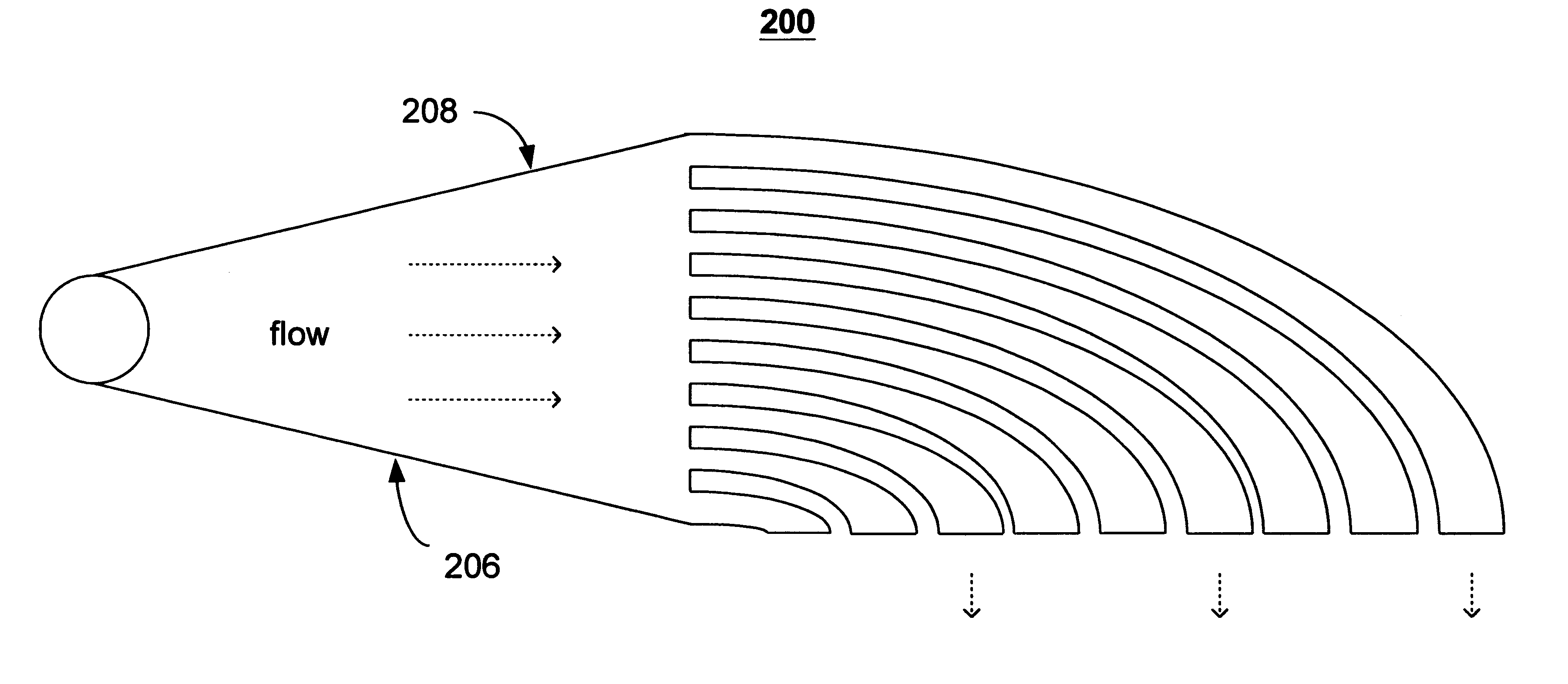
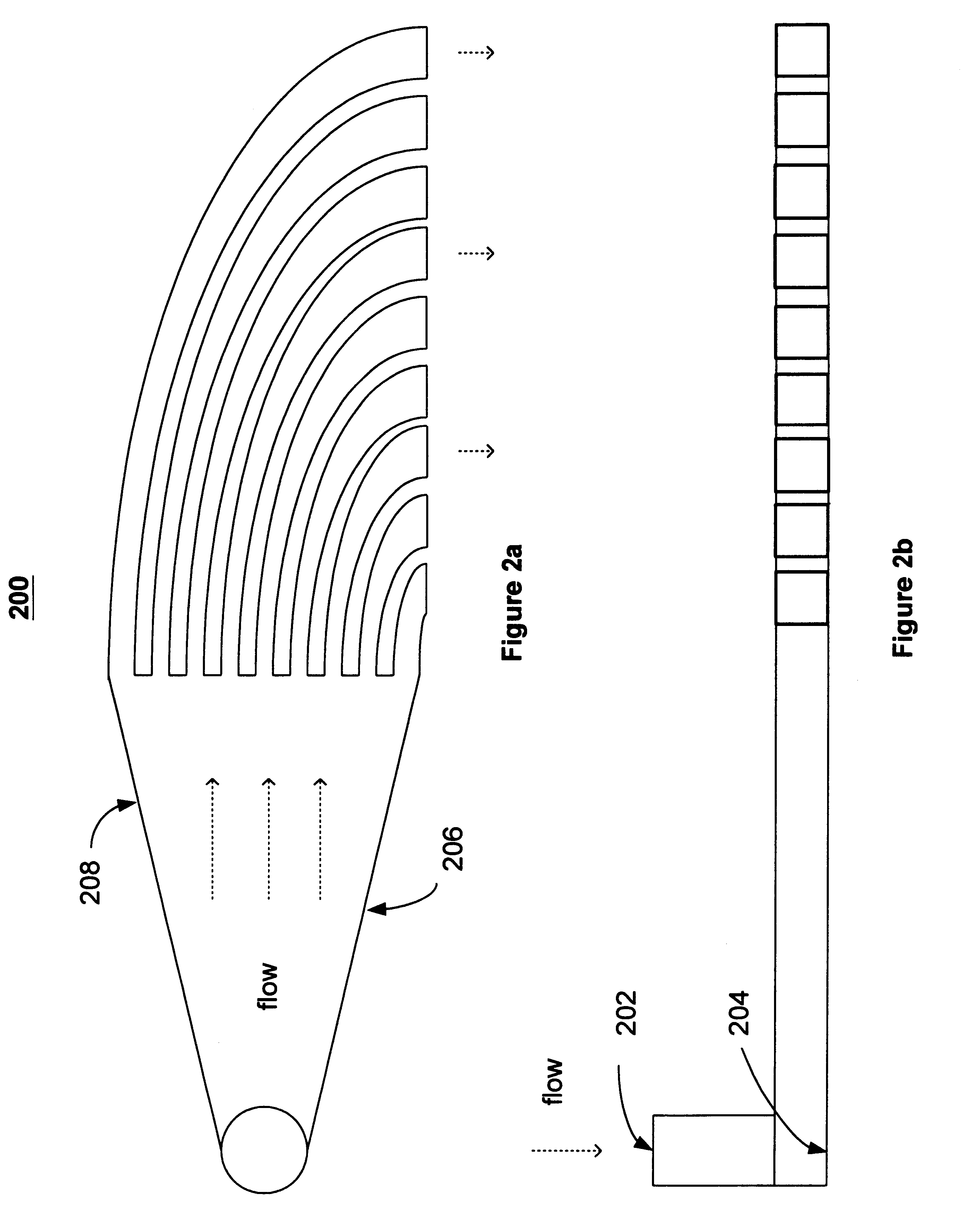
A manifold can be constructed in accordance with the invention as follows. With reference to FIG. 2, a manifold 200 can be constructed to comprise an inlet 202 for a single flow of a multiphase fluid (e.g., Zinc solid particles in a KOH liquid solution). The manifold is constructed so that the single flow impacts the base surface 204 of the inlet 202 at a 90 degree angle to the flow at a point on the base surface (e.g., the stagnation point), and can thus generate a plurality of redirected flows moving radially outward from the stagnation point and perpendicular to the original single flow. Two walls of the manifold, 206 and 208, capture only a portion of the plurality of redirected flows and further guide this portion across a predetermined distance from the stagnation point to the inlets of nine separate channels. In the case of a manifold having 9 channels comprising a 3 mm.times.10 mm rectangular cross section, this predetermined distance can be about one inc...


PUM


Abstract

A method and apparatus for converting single multiphase fluid flow into plural multiphase fluid flows having substantially uniform composition and flow properties. A manifold comprises an enclosure having an inlet and an inner surface perpendicular to the inlet such that the incident angle of input flow impacts the surface to form a stagnation point whereby an intermediate flow is deflected along the surface substantially symmetrically outward from the stagnation point and channeled to a plurality of parallel fluid outlets connected to the enclosure. The distance between the stagnation point and the plurality of outlets is selected to maintain substantially equivalent fluid pressures and uniform flow rates at the outlets. A preferred embodiment of the manifold channels the intermediate flow between two walls forming a triangular shaped nozzle directing the flow from the stagnation point to the base of the triangle for communication of electrolyte to a metal-based fuel cell through the plurality of outlets.

Description

This invention relates generally to fluid flow in a manifold, and more particularly, to the conversion of single channel multiphase fluid flow into multi-channel multiphase flows having uniform flow properties.RELATED ARTFluid manifolds have a variety of useful industrial applications, some of the more common being fuel supply and exhaust systems for internal combustion engines. These are typical examples of systems using manifolds to channel single phase fluids, such as liquid fuel or gaseous exhaust. Manifolds are also used for communicating multiphase fluids, which consist of two or more components having different phases, e.g. a mixture of liquid and solid particles. One application for multiphase manifolds is in metal-based fuel cells, where fuel in the form of metal particles is entrained in a flow of electrolyte solution, and delivered via a channel to a cell or combination of cells from which electricity is derived by means of oxidation reduction.A manifold for dividing a si...

Claims


Application Information

Patent Timeline
IPC IPC(8): H01M12/06H01M12/00H01M8/04
CPCH01M8/04186H01M12/06Y02E60/50Y10T137/0396Y10T137/85938
Inventor PINTO, MARTIN DE TEZANOS
Owner METALLIC POWER INC
Learn More