
Optical recording medium

a technology of optical recording medium and hybrid disk, which is applied in the direction of photomechanical equipment, instruments, transportation and packaging, etc., can solve the problems of not achieving satisfactory properties, unable to provide adequate modulation factor, and difficult to provide signal amplitude (recording modulation factor), etc., and achieves favorable effects

Inactive Publication Date: 2004-01-06
MITSUI CHEM INC
View PDF7 Cites 12 Cited by
  • Summary
  • Abstract
  • Description
  • Claims
  • Application Information

AI Technical Summary

Benefits of technology

This approach enables the creation of hybrid disks with enhanced recording and reproduction capabilities in both ROM and R regions, facilitating mass production and ensuring compatibility with DVD players.

Problems solved by technology

Although a hybrid disk using an organic dye as a recording film has been standardized for CDR, providing a signal amplitude (recording modulation factor) is more difficult in an ROM region than an R region and therefore, satisfactory properties have not been achieved.
It is because a recording layer comprising a dye is formed not only on a pre-groove in the R region but also on a pre-pit in the ROM region so that the same pre-pit shape as that in a commercially available CD does not give an adequate modulation factor.
This technique may, however, have drawbacks that it generally requires difficult stamper cutting of two beams in production, and that a recording signal may be degraded because a relatively shallower groove has a V shape.
Boundary control is, however, difficult from an R region to an ROM region or an ROM region to an R region.
In particular, it cannot be a practical solution in the light of compatibility in reproduction with a CD or DVD player.
Such an approach cannot be, of course, applied to a mass production.

Method used


Image

  • Optical recording medium
  • Optical recording medium
  • Optical recording medium

Examples


Embodiment Construction

1 TO 8 AND COMPARATIVE EXAMPLES 1 TO 8

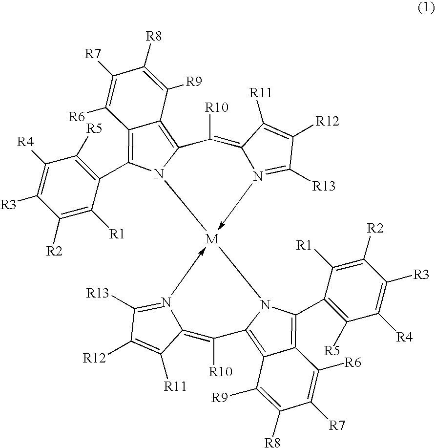
A 20 g / L solution of one of pyrromethene dyes represented by formulas (A) to (C) in ethylcyclohexane was spin-coated on an injection-molded polycarbonate substrate with a thickness of 0.6 mm and a diameter of 120 mm.phi. having a spiral groove with a pitch of 0.74 .mu.m and a pre-pit in a part of a lead-in region on the extension lines of the pre-groove to form a dye layer. On the dye layer was deposited by sputtering an Au reflective layer to 100 nm. Then, on the product was applied a UV curable resin SD-17 (Dainippon Ink And Chemicals, Inc.) and it was cured by UV. On the resin layer was laminated a polycarbonate substrate with a thickness of 0.6 mm as described above via Z8412 (JSR) radical adhesive, to prepare an optical recording medium.

The optical recording medium was evaluated for a signal modulation factor (I14 / I14H) according to DVD specifications for a pre-pit using a disk tester "DDU-1000" (Pulstec Industrial Co., Ltd.) at wavelength:...


PUM

PropertyMeasurementUnit
refractive indexaaaaaaaaaa
thicknessaaaaaaaaaa
reproduction wavelengthaaaaaaaaaa

Abstract

A recordable optical recording medium comprising a recording layer containing an organic dye which can absorb a laser beam and a metal reflective layer directly or via another layer on a transparent supporting substrate having a pre-groove and a pre-pit, wherein the organic dye has a refractive index nk of 2.2 or more at a reproduction wavelength lambda2; in relation to the reproduction wavelength lambda2, the depths of the pre-groove and the pre-pit on the substrates are more than lambda2 / 4; and the following equations are satisfied:wherein r is a recording laser beam diameter represented by lambda1 / NA where lambda1 is a recording wavelength [mum] and NA is a numerical aperture for an object lens; wg [mum] and thetagr are a half value width and a cross-section tilting angle in a substrate radial direction for the pre-groove, respectively; and wp [mum], thetapr and thetapt are a half value width, a cross-section tilting angle in a substrate radial direction and a cross-section tilting angle in a tangential direction for the pre-pit, respectively.

Description

This invention relates to an optical recording medium on which information can be recorded and / or reproduced using a laser beam. In particular, it relates to a hybrid type high-density optical recording medium which is a recordable recording medium allowing recording with a higher density than a CD and comprises a pre-pit and a pre-groove on a substrate.Among disk media for optical recording, a recordable compact disk on which recording can be performed only once, and has been popularly used because of its compatibility with a common read-only CD-ROM. For a digital versatile disk (DVD) with a higher recording density than a CD, recordable media have been developed, among which a recordable DVDR is expected to become popular because of its higher compatibility with a DVD-ROM. These recordable media use an organic dye in a recording layer, in which a dye irradiated with a laser beam is locally heated to undergo chemical and / or physical change such as decomposition, deformation, vapori...

Claims


Application Information

Patent Timeline
Patent Type & Authority Patents(United States)
IPC IPC(8): B32B3/02G11B7/24G11B7/007G11B7/013G11B7/24079G11B7/24085G11B7/246G11B7/2492G11B7/258
CPCG11B7/24079G11B7/24085G11B7/2492G11B7/246Y10T428/21G11B7/258G11B7/2407
Inventor KOIDE, AKIHIROINATOMI, YUJIKOIKE, TADASHI
Owner MITSUI CHEM INC
Learn More