
Method for testing and guaranteeing that skew between two signals meets predetermined criteria

a technology of skew and signal, applied in the field of testing semiconductor devices, can solve the problems of incorrect data being read or written, computer chips become extremely complex, and incorrect data may be read

Inactive Publication Date: 2003-12-02
GOOGLE LLC
View PDF7 Cites 16 Cited by
  • Summary
  • Abstract
  • Description
  • Claims
  • Application Information

AI Technical Summary

Benefits of technology

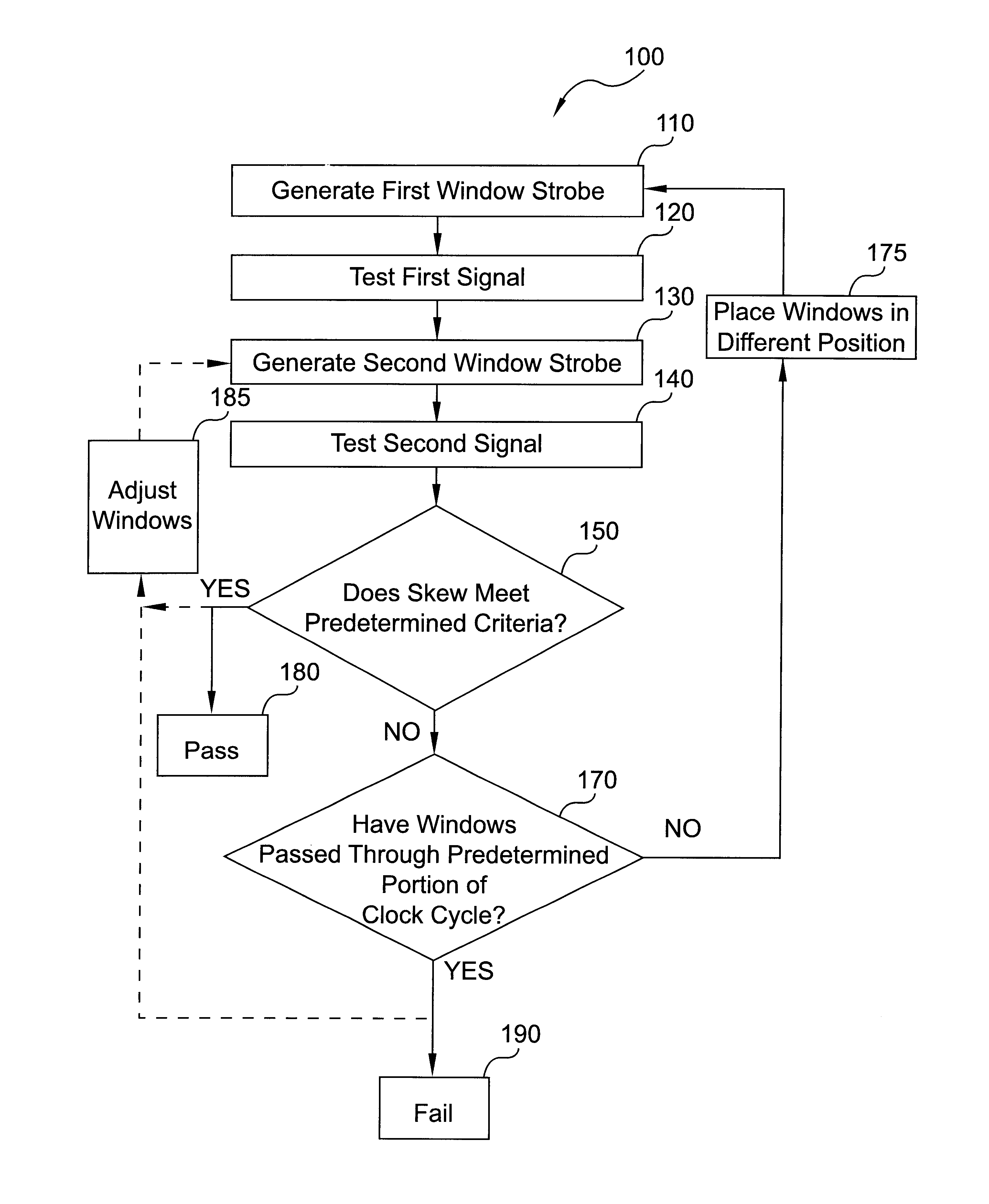
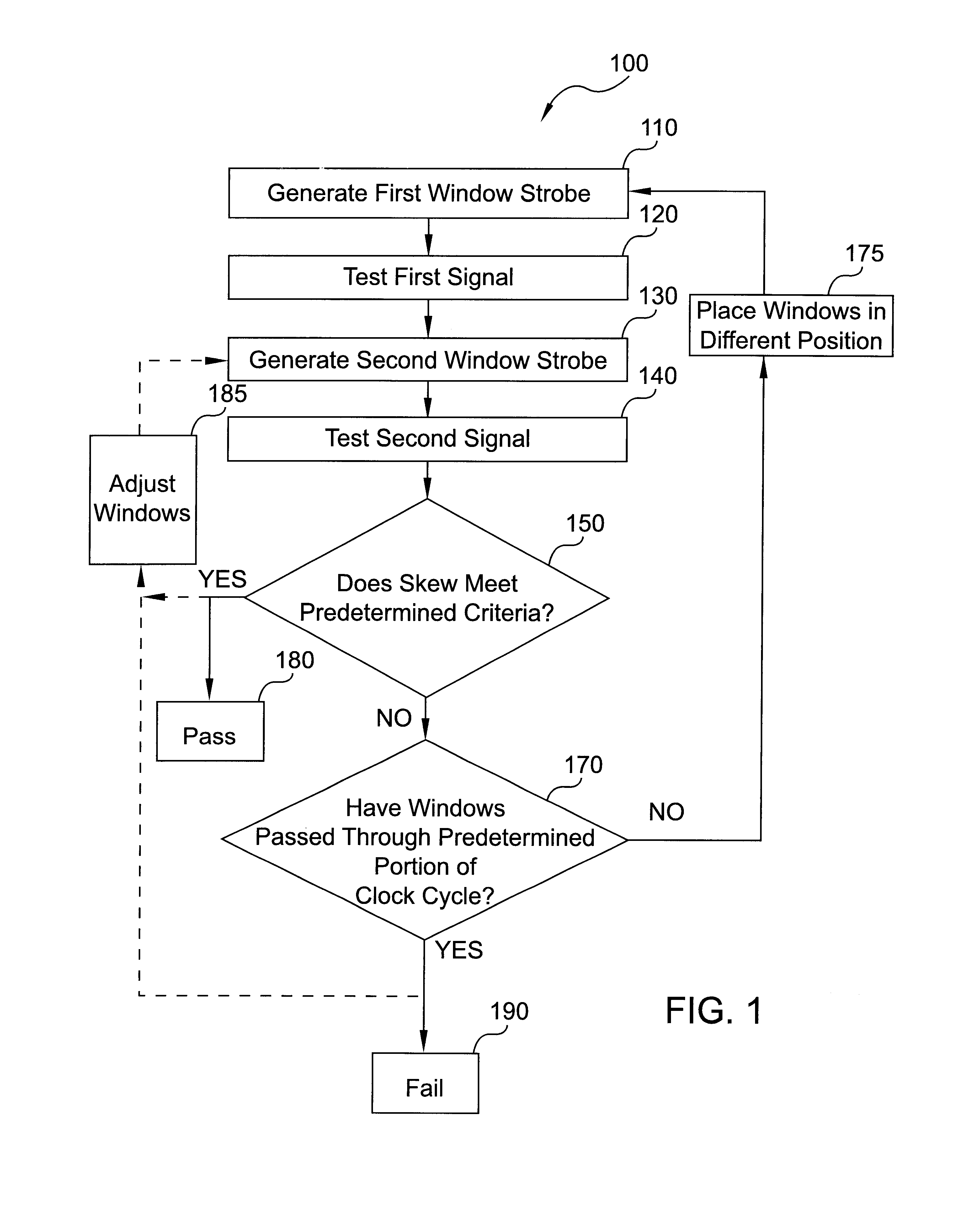
To overcome these problems, the present invention generates two window strobes and uses the two window strobes to determine if skew between two signals meets predetermined criteria. One of the window strobes is used to test one of the signals, and the other window strobe is generated relative to the first window strobe. The second window strobe tests the other signal (or signals, if they are data signals). From the tests of the two window strobes, it can be determined if the skew between the first and second signals meets predetermined criteria. In particular, the two window strobes are placed relative to each other and to the signals being tested in such a way that when both window strobes indicate passing conditions, skew between the two signals is guaranteed.

Problems solved by technology

Computer chips have become extremely complex: Millions of logic devices can be made to fit on one chip.
If the signals do not meet skew requirements, it is possible for incorrect data to be read or written.
If this is not the case, incorrect data may be read.
This "guardbanding" requirement often results in over testing the device and results in unnecessary yield loss.
However, due to p- and n-channel processing skews, data pattern dependent noise, and physical layout mismatches of the chip, there can exist a skew between valid data strobe and valid data.
With the current installed base of manufacturing testers, it becomes hard to measure the data strobe-to-data skew.
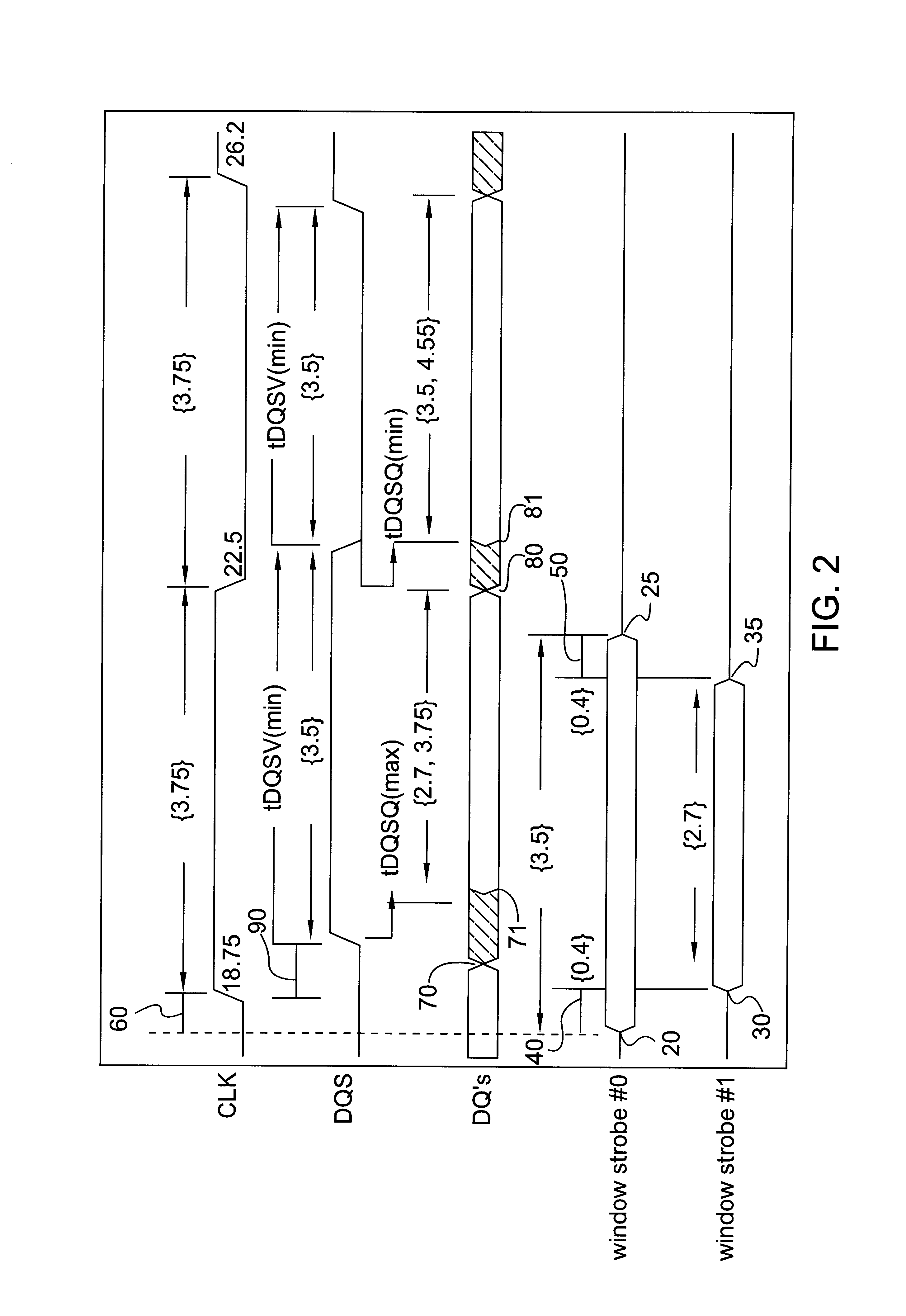
The data strobe-to-data skew is typically in the range of 500 to 600 ps and is very difficult if not impossible to measure directly on a tester using a single "edge strobe" in a similar manner to the method used to measure tAC(max).
Because the data strobe generated by the RAM is not fixed with respect to the input clock, and because the data is not fixed with respect to the clock or the data strobe, an "edge strobe" measurement is ineffective in measuring the skew between data strobe and the data signals.
DDR DRAMS contain a digital locked loop (DLL) on the chip that aligns both the data strobe and data to the system clock during read cycles; however, the DLL is not perfectly accurate.
It has resolution errors, and will be off by some number of picoseconds.
Secondly, the important signals being measured are the data skew.
Because there are errors in the placement of the edge strobes, it is very hard to measure 500-600 ps without over- or under-testing the actual skew.
This would cause edge strobe 2 to strobe invalid data, which would indicate an error for a cycle that is within specifications.
Commonly, edge strobes can have errors in edge strobe placement of 300 or more picoseconds.
Thus, it is impractical to try to measure a data strobe-to-data skew of 500 ps with two edge strobes fixed relative to the system input clock, with each strobe having placement accuracy error up to 300 ps, and where the skew has cycle-to-cycle variability.
However, this results in significant cost and renders current tester useless.
However, these are only estimates or theoretical assumptions and actual devices may fail outside the statistical limits.

Method used


Image

  • Method for testing and guaranteeing that skew between two signals meets predetermined criteria
  • Method for testing and guaranteeing that skew between two signals meets predetermined criteria
  • Method for testing and guaranteeing that skew between two signals meets predetermined criteria

Examples


Embodiment Construction

To overcome the problems of the prior art, the present invention generates two window strobes and uses the two window strobes to determine if skew between two signals meets predetermined criteria. One of the window strobes is used to test one of the signals, and the other window strobe is generated relative to the first window strobe. The second window strobe tests the other signal (or signals, if they are data signals). From the tests of the two window strobes, it can be determined if the skew between the first and second signals meets predetermined criteria. In particular, the two window strobes are placed relative to each other and to the signals being tested in such a way that when both window strobes indicate passing conditions, skew between the two signals is guaranteed.

The present method is applicable to any two signals where the first signal is longer in time than the second signal and where there is some minimum or maximum relative skew between the two signals. In the most ...


PUM

PropertyMeasurementUnit
valid time periodsaaaaaaaaaa
timeaaaaaaaaaa
offset timeaaaaaaaaaa

Abstract

To overcome these problems, the present invention generates two window strobes and uses the two window strobes to determine if skew between two signals meets predetermined criteria. One of the window strobes is used to test one of the signals, and the other window strobe is generated relative to the first window strobe. The second window strobe tests the other signal (or signals, if they are data signals). From the tests of the two window strobes, it can be determined if the skew between the first and second signals meets predetermined criteria. In particular, the two window strobes are placed relative to each other and to the signals being tested in such a way that when both window strobes indicate passing conditions, skew between the two signals is guaranteed.

Description

1. Technical FieldThis invention relates to the field of testing semiconductor devices. More specifically, the invention relates to a method for testing and guaranteeing that skew between two signals meets predetermined criteria.2. Background ArtComputer chips have become extremely complex: Millions of logic devices can be made to fit on one chip. Because of this complexity, it is essential that these chips be tested. Prior to use, the computer chip is placed into a tester to ensure that signals meet timing requirements. One important criterion for testing signals is skew. Skew is the difference in arrival time, at a particular location, between two signals. For some signals, it is desired that there be very little skew. Generally, limits are placed on the skew between two or more signals so that the signals arrive at a specific location at about the same time. If the signals do not meet skew requirements, it is possible for incorrect data to be read or written.Skew is particularly ...

Claims


Application Information

Patent Timeline
Patent Type & Authority Patents(United States)
IPC IPC(8): G01R31/3193G01R31/28G01R31/30G11C29/04G11C29/50H04L25/14
CPCG01R31/3016G01R31/31937H04L25/14G11C29/50G11C29/50012G11C29/028G11C11/401
Inventor CORBIN, WILLIAM R.MONTY, DAVID P.NELSON, ERIK A.NORRIS, ALAN D.TOMASHOT, STEVEN W.CHAPMAN, DAVID E.FISCUS, TIMOTHY E.
Owner GOOGLE LLC
Learn More