
Method and a device for adjusting the pitch and stopping the rotation of the blades of a wind turbine

a technology of wind turbine blades and devices, which is applied in the direction of propellers, propulsive elements, water-acting propulsive elements, etc., can solve the problems of large disadvantage, large wear of motors, and continuous operation of motors, so as to reduce the overall efficiency of wind turbines and high energy consumption.

Inactive Publication Date: 2003-08-26
NEG MICON
View PDF7 Cites 89 Cited by
  • Summary
  • Abstract
  • Description
  • Claims
  • Application Information

AI Technical Summary

Benefits of technology

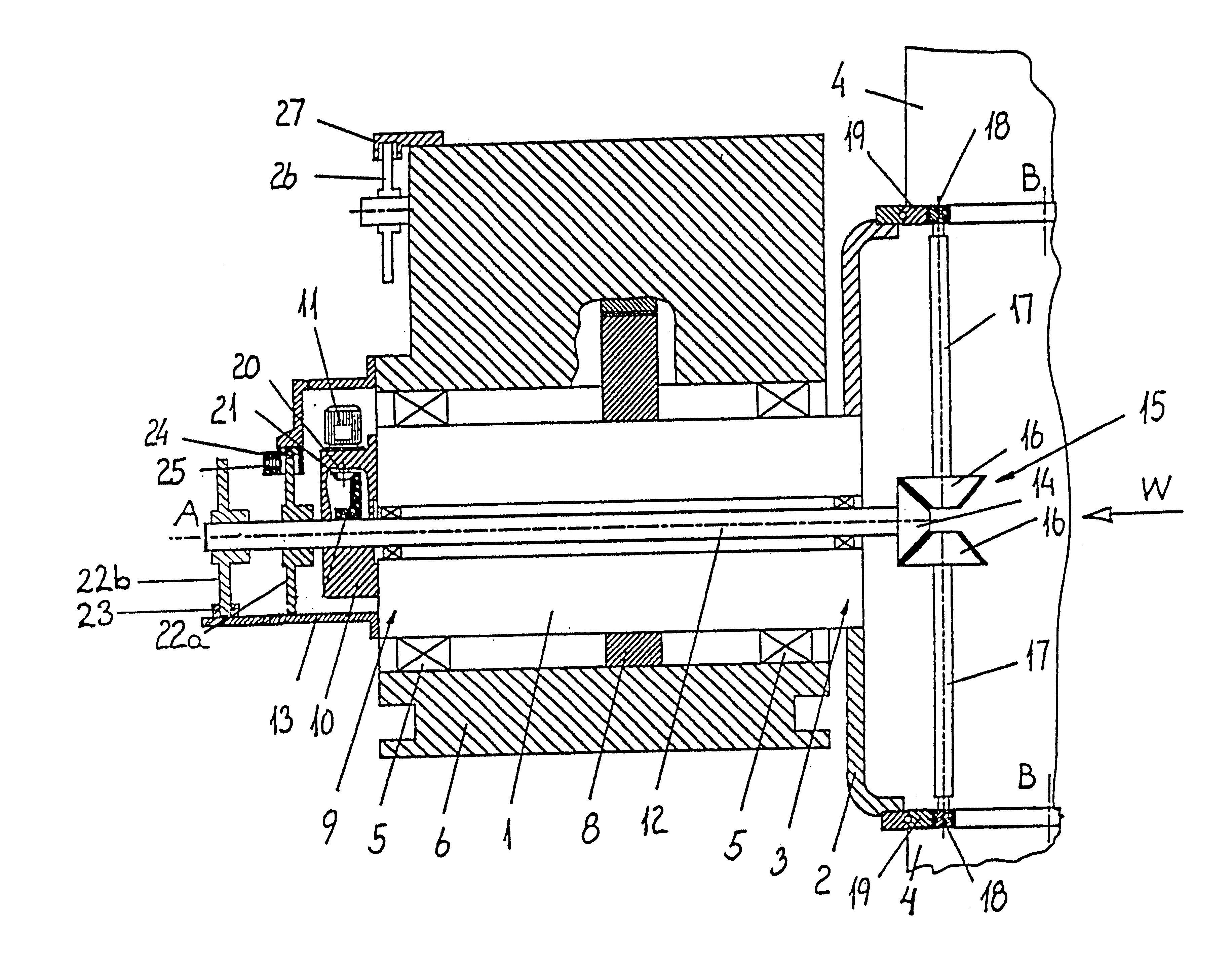
Bringing the rotation of the pitch motor to a standstill relative to the main shaft while the said main shaft is rotating under normal operational conditions provides several advantages. Firstly, the wear of the pitch motor will be substantially reduced compared with a method continuing the rotation of the pitch motor rotation shaft also under normal operational conditions when correct pitch of the blades has been established.
Mounting the motor on the main shaft provides the possibility of no longer having to exert control over the relative speed of rotation of the motor and the rotational shaft. The motor does not rotate if the correct pitch of the blades has been established. Any less exact tolerances and any wear to the mechanical parts will have no essential influence on maintaining the correct pitch of the blades, the motor controlling the pitch respective to given values such as the speed of rotation of the main shaft, the wind speed, etc, and the load on the mechanical parts will be purely static once the correct pitch has been established, since there are no dynamic relations between the motor, the main shaft and the bevel gear once the correct pitch of the blades has been established. Furthermore, there is no need for any disengagable coupling between the drive axle of the pitch motor and the synchronizing shaft. This also ensures that no mechanical wear or even mechanical failure occurs which may impede the controlling of the pitch of the blades and reduce the overall efficiency of the wind turbine.
Mounting a brake further provides the advantage that static relations between motor, main shaft, bevel gear and blades are not to be maintained by the motor operating as a brake to maintain static relations, these relations between main shaft, bevel gear and blades being instead maintained by a brake to relieve the motor when the correct pitch of the blades has been established and the motor therefore is not operating.
Bringing the rotation of the main shaft to a standstill is a novel feature, partly by the mechanism controlling the pitch of the blades being new, and partly by the main shaft coming automatically to a standstill in case of current failure of the motor controlling the blade pitch, the so-called pitch motor. Stopping takes place in such a way that the main shaft is not brought to a complete halt, but allowed to rotate around a point of equilibrium. This method of the invention allows the main shaft to rotate alternately and partly in a forward and partly in a reverse direction of rotation. This means that the main shaft bearings and the rotation collar bearings are in motion and therefore will not fail because of any unilateral static load nor because of any dynamic spot load when the main shaft and the rotation collars are completely stopped, nor will they be insufficiently greased by the slow turning of the main shaft in a positive direction of rotation only.
a main shaft rotatably connected to a base part of the wind turbine, and at least one blade connected to the main shaft, the connection enables rotation of the blade about a longitudinal axis of the blade,

Problems solved by technology

This is a major disadvantage.
Second, the motor has to operate continuously to maintain the correct blade pitch.
This results in extensive wear of the motor and entails large energy consumption for operating the motor.
Furthermore it is necessary to control the speed of rotation variably and continuously relative to the variations in the speed of rotation of the main shaft, and the motor control risks being constantly somewhat behind compared with the main shaft, and consequently an optimal pitch angle of the blades cannot always be obtained.
Furthermore, the device is not capable of stopping or limiting the rotation of the main shaft in a controlled manner in case the motor cannot rotate because of e.g. current failure of the motor shaft rotation.
The main shaft will, however, stop rotating after a while, since the blades once the motor no longer rotates synchroneously with the main shaft will soon be pitched at angular positions which are not optimal for the main shaft rotation.
However, the need for a clutch or other means of coupling the pitch motor and the synchronizing shaft by means of a disengagable coupling means is a disadvantage.
The clutch may be worn or may even failure, which makes it impossible to control the pitch of the blades.
If the pitch of the blades cannot be controlled then the wind turbine is not able to produce the maximum amount of effect or may even not be able to produce effect at all.
This is time consuming which decreases the overall efficiency of the wind turbine.
Furthermore it involves costs of a technician and the costs of spare parts.
Lastly using a clutch or other disengagable coupling means may delay controlling of the pitch of the blades when as example a clutch has to be activated before controlling of the pitch of the blades can take place.
However, this prior art necessitates the use of a pitch motor for each of the blades.
Finally, the pitch motor is used exclusively for controlling the pitch of the blades and is not used simultaneously for maintaining a speed of rotation of the drive wheel relative to the speed of rotation of the main shaft, a function which entails further technical control difficulties.
This also ensures that no mechanical wear or even mechanical failure occurs which may impede the controlling of the pitch of the blades and reduce the overall efficiency of the wind turbine.
If this step is included in the method, the pitch altering process must be initiated by releasing the synchronizing shaft relative to the main shaft otherwise a difference in angular rotation between the two shafts may not be accomplished.

Method used


Image

  • Method and a device for adjusting the pitch and stopping the rotation of the blades of a wind turbine
  • Method and a device for adjusting the pitch and stopping the rotation of the blades of a wind turbine
  • Method and a device for adjusting the pitch and stopping the rotation of the blades of a wind turbine

Examples


Embodiment Construction

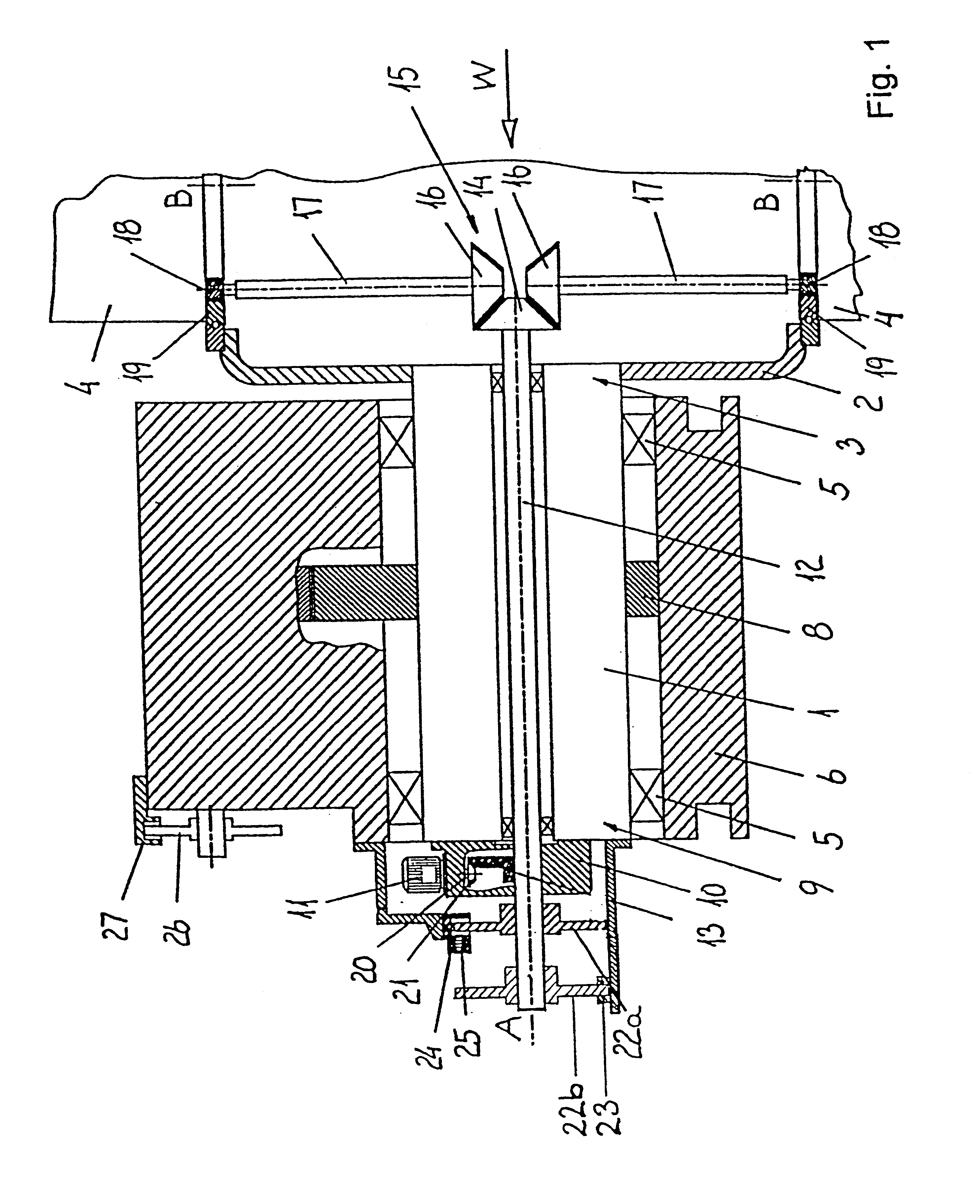
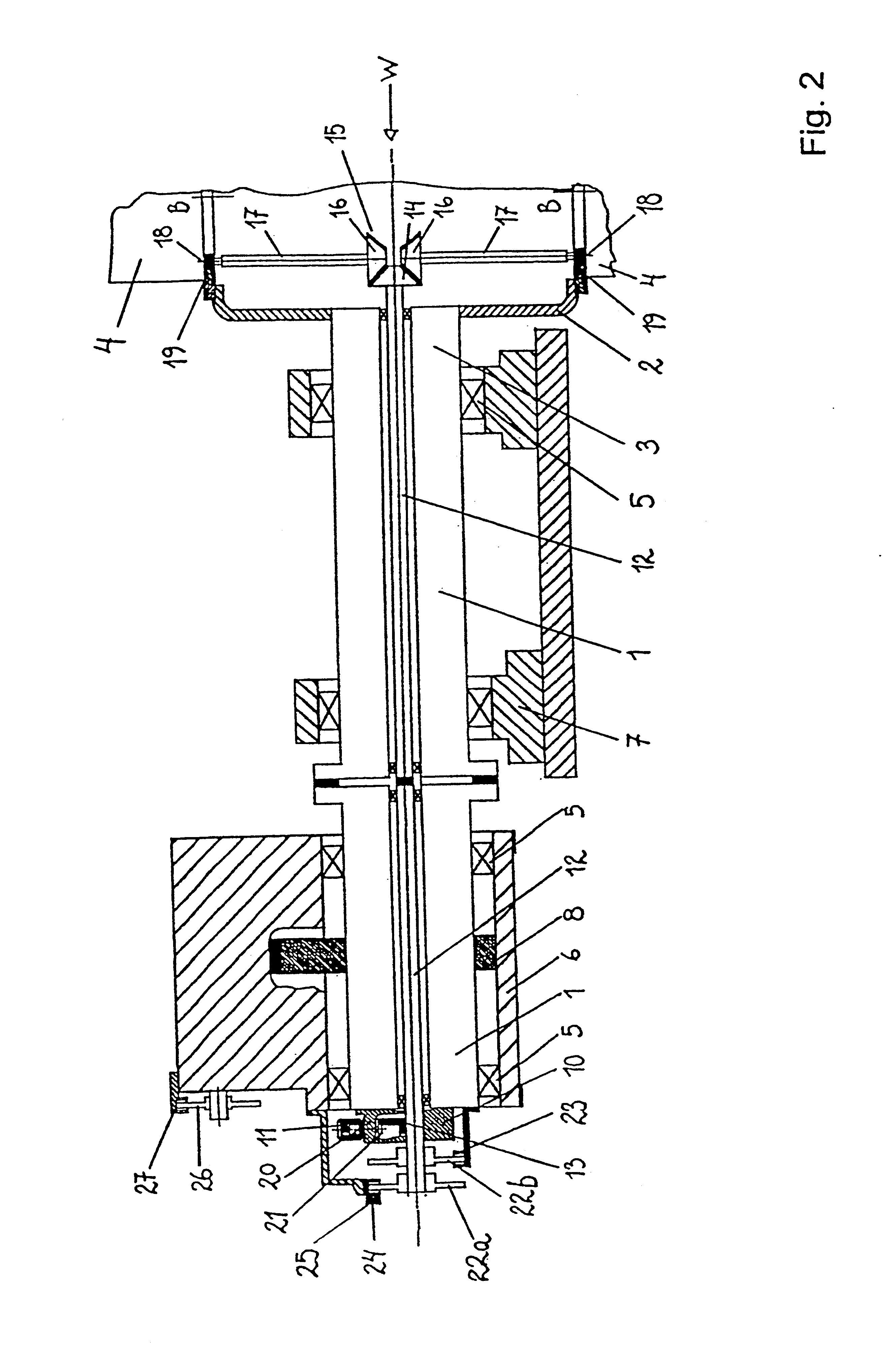
FIG. 1 and FIG. 2 illustrate a part of a drive mechanism of a wind turbine, FIG. 1 showing a first preferred embodiment where the main shaft of the blades is integrated in the main shaft of transmission, and FIG. 2 showing a second preferred embodiment where the main shaft of the blades is separate relative to the main shaft of transmission. Each of the two embodiments technically operates in the same way in relation to the invention.

In an alternative embodiment of the present invention (not shown) the generator is a multipole generator and the blades 4 are connected to the rotor of that generator. Thereby the main shaft 1 is either not present or is constituted by the shaft of the generator. In both cases the transmission connecting the generator to the mains shaft is not present.

The drive mechanism comprises a longitudinal main shaft 1 of a rotor. The rotor has a hub which is secured to the front end 3 of the main shaft and which faces a wind direction W. On the hub blades 4 are m...


PUM


Abstract

A method and mechanism for adjusting / controlling the pitch of at least one blade of a wind turbine relative to a wind direction parallel to a longitudinal main shaft of the wind turbine use a mechanism with a motor for rotating drive wheels in the angle gear around a longitudinal blade shaft via drive wheels of an angle gear. The method and mechanism can stop the complete turning of a main shaft of a wind turbine having a motor to rotate a drive pinion in an angle gear via a drive wheel, the angle gear being meant to pitch at least one blade around a longitudinal axis.

Description

The present invention relates in a broad aspect to a device and a method for adjusting the pitch of a wind turbine and for stopping the rotation of the blades of a wind turbine.BACKGROUND OF THE INVENTION AND INTRODUCTION TO THE INVENTIONIn one aspect, the present invention relates to a method of adjusting the angular position of at least one blade of a wind turbine, the said wind turbine comprising a bevel gear and a motor for the rotation of a drive wheel of the bevel gear and drive pinions of the bevel gear for turning at least one blade at an angle, this at least one blade being turned at an angle by the drive pinions, the said drive pinions being rotated by the drive wheel, and the drive wheel being rotated by the motor relative to the main shaft. The invention also relates to a mechanism for controlling the pitch of at least one blade of a wind turbine relative to a wind direction parallel to a longitudinal main shaft of the wind turbine, the said mechanism comprising a motor ...

Claims


Application Information

Patent Timeline
Patent Type & Authority Patents(United States)
IPC IPC(8): F03D7/02F03D7/00
CPCF03D7/0224F03D7/0248F03D7/0268F05B2260/72F05B2260/76F05B2260/902F05B2270/328Y02E10/723Y10S415/908Y02E10/72
Inventor VILSBOLL, NIELS
Owner NEG MICON
Learn More