Emergency-deceleration condition transducer, controlling circuit for emergency-deceleration condition signal, and emergency brake lamp
- Summary
- Abstract
- Description
- Claims
- Application Information
AI Technical Summary
Benefits of technology
Problems solved by technology
Method used
Image


Examples
Embodiment Construction
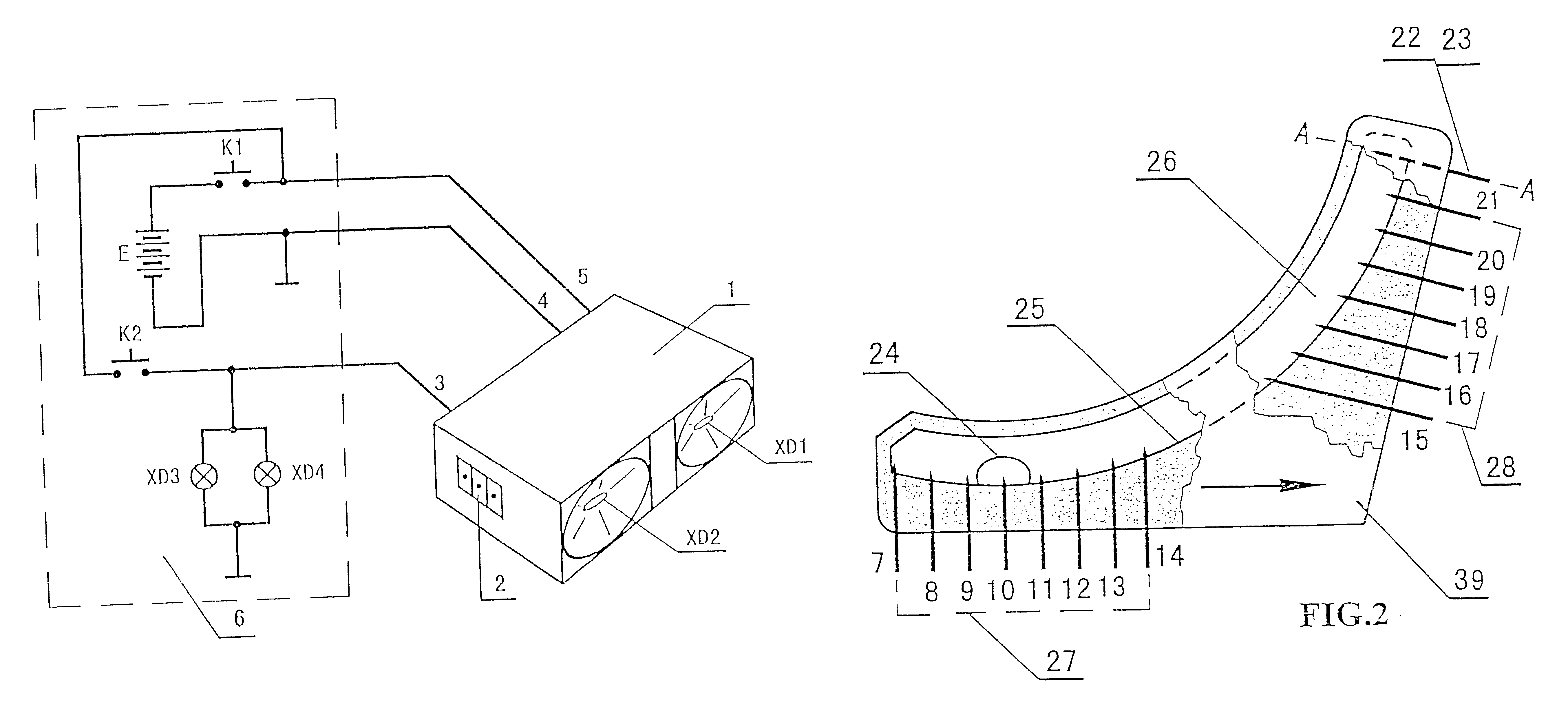
An emergency brake lamp 1, shown in FIG. 1 and controlled by an emergency-deceleration transducer, is mounted above the back row seats in the vehicle or on the tail of the vehicle. The lamp 1 has three input lines which are respectively used for a negative electrode 4, a positive electrode 5 and an emergency brake lamp light signal 3 which is realized by the flashing of the xenon arc lamps XD1, XD2. Output terminals 2 are function extension interfaces, which can be connected with an electronic apparatus such as a special radio transmitting-receiving warner. The dash lines show an automobile circuit 6, in which E is a battery, K1 a lock control power supply switch, K2 a brake lamp switch, and XD3, XD3 are brake tail lamps.
When a driver turns on the lock control switch K1 (i.e. the power supply switch on board), the emergency brake lamp1 controlled by the emergency-deceleration transducer enters into a monitoring condition. If K2 is closed, it means that the brake is being applied, an...
PUM
 Abstract
Description
Claims
Application Information
 - R&D
- Intellectual Property
- Life Sciences
- Materials
- Tech Scout
- Unparalleled Data Quality
- Higher Quality Content
- 60% Fewer Hallucinations
Browse by: Latest US Patents, China's latest patents, Technical Efficacy Thesaurus, Application Domain, Technology Topic, Popular Technical Reports.
© 2025 PatSnap. All rights reserved.Legal|Privacy policy|Modern Slavery Act Transparency Statement|Sitemap|About US| Contact US: help@patsnap.com