
Threaded fastener having a thread crest greater than its thread root

Inactive Publication Date: 2003-06-03
REED LOUISE A
View PDF15 Cites 41 Cited by
  • Summary
  • Abstract
  • Description
  • Claims
  • Application Information

AI Technical Summary

Benefits of technology

A further object of the present invention is to provide a device as characterized above which has greater resistance to axial forces, radial forces and bending moments.
A further object of the present invention is to provide a device as characterized above in which the variation in the thread geometry of the fastener allows initial easy starting of the threaded fastener into the associated bore and is subsequently followed by an increase in the rotating force required to incrementally advance the fastener.
A further object of the present invention is to provide a device as characterized above which is durable in construction, extremely safe to use and lends its self to mass production techniques.

Problems solved by technology

While several of these patents teach the use of an element which appears to benefit from dovetail geometry, none provide interconnection between a threaded fastener and a correspondingly contoured bore in which the fastener meets with gradually increased resistance, providing an interference fit as the fastener becomes progressively engaged.
This radial spreading force often overpowers the strength of the piece it is tightened into and causes the piece to crack.
Reversal of the prior art spreading force will greatly increase the life of threaded holes which affects the life and serviceability of the part.
This self-engagement will result in the threads of the pin being drawn deeper into the side wall of the threaded hole which when tightening occurs and, results in halting continued forward rotation (advancement) of the pin.
Spreading force causes cracks.
Threaded holes that are too close to an edge are prone to cracking.
Threaded holes in soft materials are prone to stripping.

Method used


Image

  • Threaded fastener having a thread crest greater than its thread root
  • Threaded fastener having a thread crest greater than its thread root
  • Threaded fastener having a thread crest greater than its thread root

Examples


Embodiment Construction

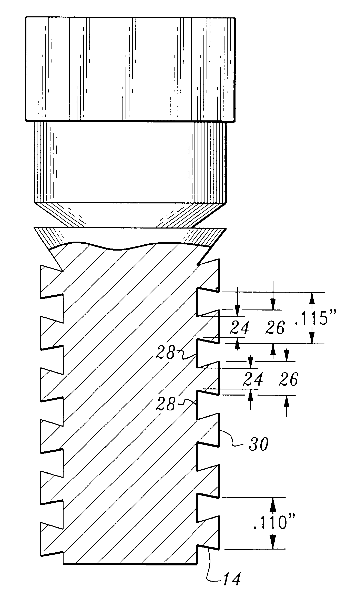
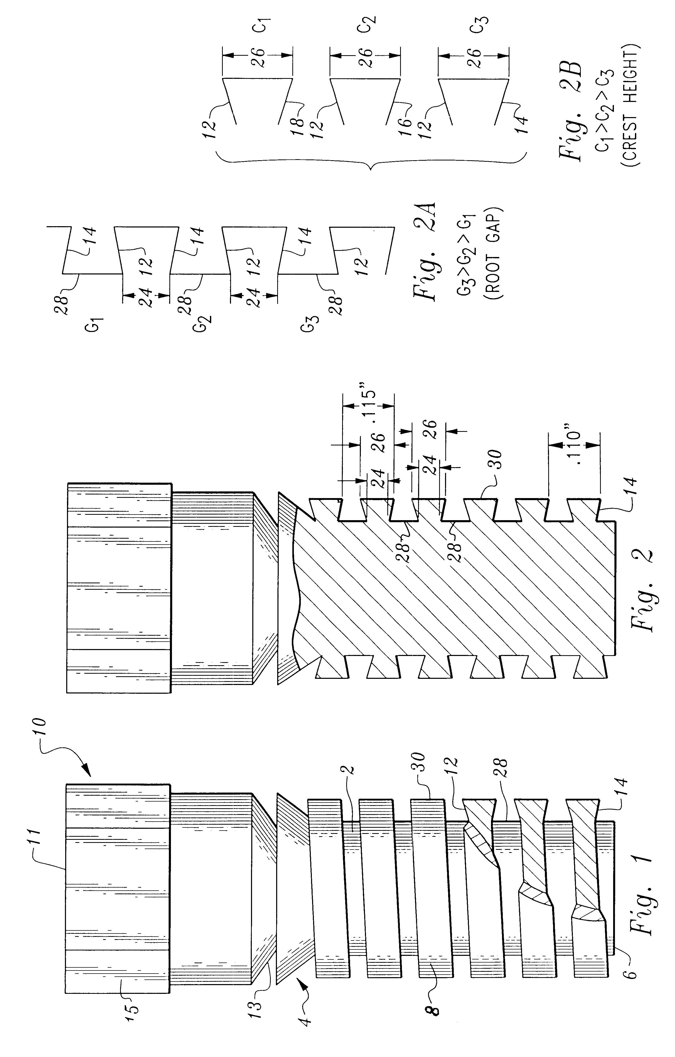
Considering the drawings, wherein like reference numerals denote like parts throughout the various drawing figures, reference numeral 10 is directed to the threaded fastener according to the present invention.

In general, the fastener 10 includes a shaft 2 preferably of substantially cylindrical configuration. The fastener 10 has a first end 4 adjacent a "top" thereof and a second end 6 defining a "bottom". Note that the use of terms such as "top", "bottom", "horizontal", etc. are made relative to the drawings appended herewith but are not intended to be directionally limiting.

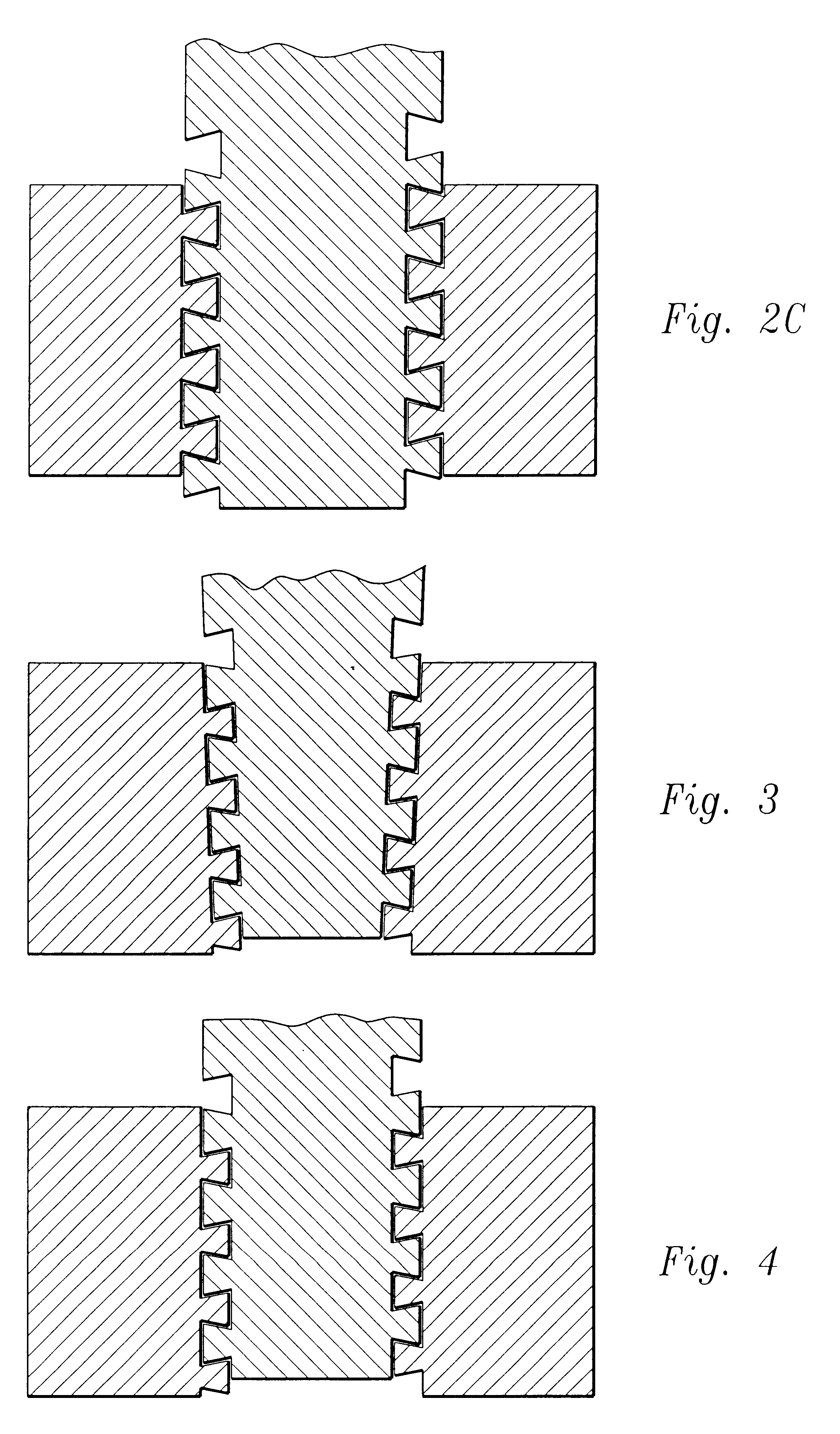
In its essence, the invention resides in the ability to provide an interference fit between the fastener with its associated bore. In one specific embodiment the threads are dovetail in section, the fastener when tightened induces radially inward forces as well as compressive forces which provide a fastener of improved holding power. The degree of interference increases as the thread is advanced into the bore. ...


PUM


Abstract

A progressive (variable) pitch, interlocking thread with a tooth cross-section that is wider at its crest than at its root which creates radial clamping action when tightened into a tapped hole that has a similar thread cross-section.

Description

The following invention relates generally to fasteners. More particularly, this invention pertains to the field of fasteners having an exterior thread located peripherally about the shaft of the fastener, in which the thread spirals along a portion of the shaft. Most specifically, the thread, when taken in cross-section has a contour which increases in a dimension as it extends radially away from a root of the thread.Threaded fasteners are extremely old devices which exhibit superior holding properties over non-threaded fasteners primarily due to a higher coefficient of friction. This coefficient of friction is manifested along the inter-face of the threads to its connecting; environment. Fasteners where the threaded portion exhibits a dovetail when viewed in cross-section define one specie of threaded fastener.The following patents reflect the state of the art of which applicant is aware and is included herewith to discharge applicant's avowed duty to disclose prior art. It is resp...

Claims


Application Information

Patent Timeline
IPC IPC(8): F16B39/30F16B39/00
CPCF16B39/30
Inventor REED, GARY JACK
Owner REED LOUISE A
Learn More