
Can end manufacturing system and press therefor

Inactive Publication Date: 2003-03-18
REXAM BEVERAGE CAN
View PDF31 Cites 25 Cited by
  • Summary
  • Abstract
  • Description
  • Claims
  • Application Information

AI Technical Summary

Benefits of technology

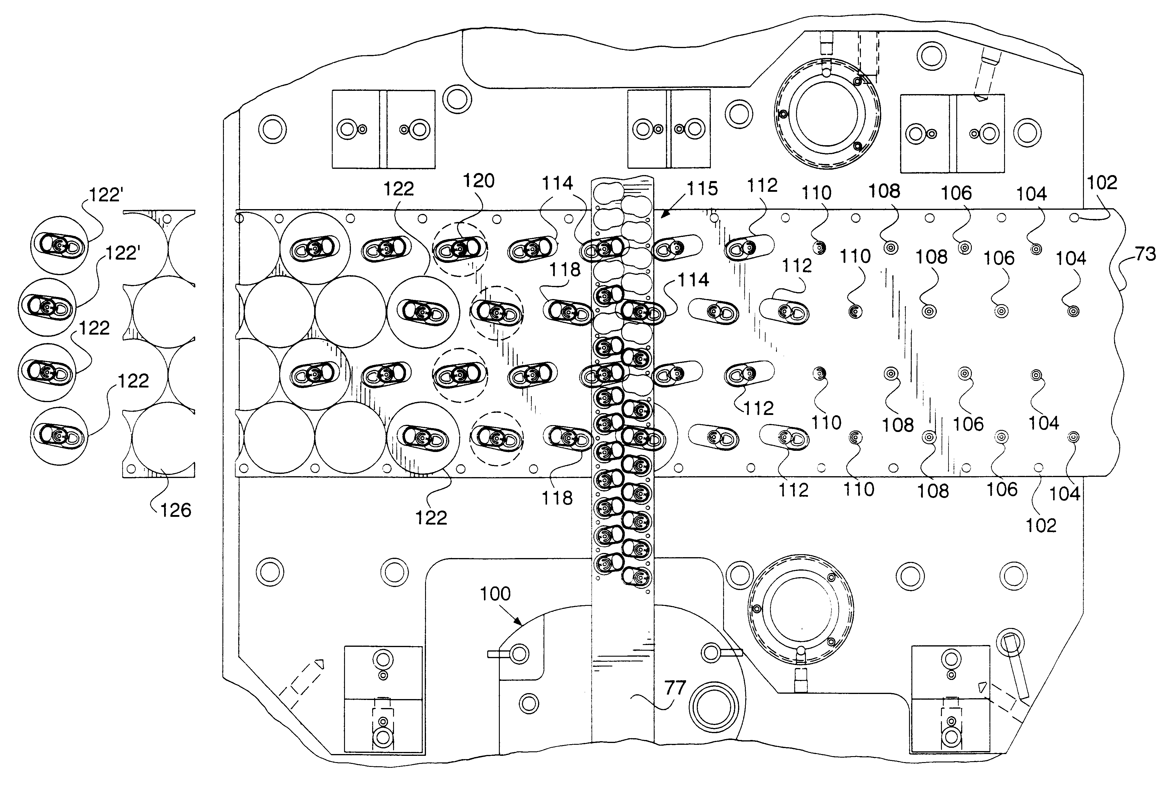
FIG. 4 is a more detailed plan view of the press of FIG. 3, showing in more det

Problems solved by technology

While the Buhrke system was put into practice and used for a period of years during the early 1980's, it was prone to problems and ultimately unsuccessful.
In particular, the void features formed in the sheet of material in the beginning of the operations in the press created an elastic condition when the sheet was indexed through the press, leading to registration problems between the sheet of material and downstream work stations that formed the closure and other features in the end.
More specifically, the void features led to relative movement between various portions of the sheet when the indexing mechanism moved the sheet through the press, resulting in a mis-alignment between the tools of the work stations and the portion of the sheet containing an end in various states of completion.
Furthermore, the machine had a relatively low metal realization since the design requires material to carry the ends through the press.
The resulting down-time to change the position of the dies, slow speed of operation, poor quality of ends due to the misalignment, and overall maintenance and metal utilization problems experienced by machines made in accordance with the '422 Buhrke patent eventually resulted in the abandonment and eventual replacement of such machines.
The Herrmann '199 patent was commercialized for a short time, but such machines were.soon abandoned and replaced.
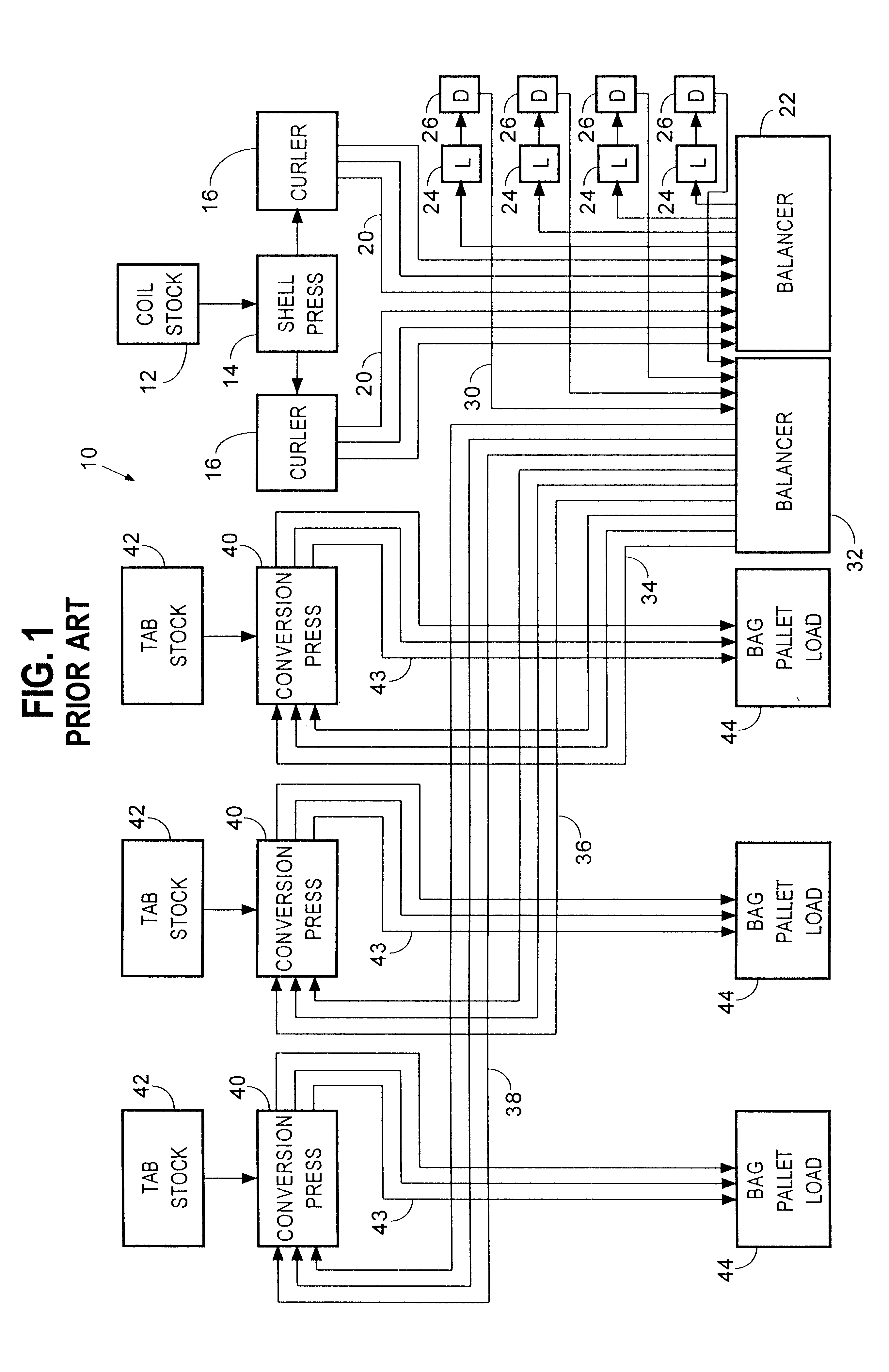
The system of FIG. 1, described below, was a much more complex and capital-intensive system than those systems used previously.
First, an enormous capital investment is required to install a system such as shown in FIG. 1.
In particular, a large amount of expensive track work is required.
The system requires two balancers and a total of four presses, all of which are very costly machines.
Further, the layout of the equipment requires a large amount of space and therefore a large building site, which increases the cost.
Construction of such a building and providing heating and cooling also increases costs.
Furthermore, the sheer number of presses and the balancers results in a system that consumes a lot of electrical power during operation, and a large number or operators and mechanics, increasing the costs further.
While the system of FIG. 1 could be modified somewhat by reducing the number of conversion presses or eliminating the dryers, the basic architecture of the prior art system based on shell presses, conversion presses, balancers and extensive track-work is a very capital, space, energy and labor intensive system.
This results in maintenance of proper alignment of the sheet with respect to the tools as the end is formed by the work stations.
If a particular problem is found with an end at an inspection station at the end of the line, the problem can be traced to the particular tool or even portion of a tool in the press.

Method used


Image

  • Can end manufacturing system and press therefor
  • Can end manufacturing system and press therefor
  • Can end manufacturing system and press therefor

Examples


Embodiment Construction

Referring now to FIGS. 2-4, a new can end manufacturing system 70 in accordance with a presently preferred embodiment of the invention will be described. Referring now in particular to FIGS. 2 and 3, the system 70 includes an end stock uncoiler 72 that supplies a continuous sheet 73 of end material, such as aluminum or steel, to a coil stock feed mechanism 72A, which supplies the sheet 73 to a press 74. Similarly, a tab stock uncoiler 76 supplies a continuous sheet 77 of tab stock to the press 74. The press 74 is shown in greater detail in FIGS. 3 and 4 and will be described in detail below. Basically, the press 74 consists of a plurality of work stations that perform various forming operations on the sheet 73 of end material, the details of which will be dictated by customer requirements, and completes the formation of the ends in the sheet of end material. Simultaneously, the press 74 has work stations that continuously form tabs in the sheet 77 of tab stock, in known fashion. One...


PUM


Abstract

Ends for cans are made in a single press, eliminating the need for separate shell and conversion presses, balancers, track work, and other equipment, as compared to existing can end manufacturing systems, while reducing floor space and capital investment requirements for installation of a new can end line. A sheet of end material or stock is introduced into the press and fed to a series of work stations. The sheet is maintained in a substantially continuous and void free state as the work stations perform forming operations on the sheet of material to form one or more ends therein. After the forming operation is complete, the end is ejected from the press. The maintenance of the sheet of material in a substantially continuous and void free state permits precise movement of the sheet through the press, and registration of the sheet relative to the tooling in the press. This precise movement and maintenance of registration results in a single press capable of operation at high speeds to produce large volumes of ends, while doing so in a reliable and cost-effective manner. In a preferred embodiment, the typical shell conversion operations are performed first on the sheet of end material, while maintaining the sheet in a substantially planar and void free state, followed by a shell forming operation in which the panel and countersink features are formed and the completed end blanked in a single stroke at the very end of the forming operations.

Description

A. Field of the InventionThis invention relates to the art of manufacturing ends for cans, such as, for example, ends that close off aluminum beverage cans, ends for cans containing human or animal foods, and ends for containers for consumer products such as tennis balls. The invention also relates to a press that is used to make can ends and the methods by which such a press operates to form an end out of a sheet or coil of stock material.B. Description of Related ArtIt is well known to draw and iron a sheet metal blank to make a thin-walled can body for packaging beverages, such as beer, fruit juice or carbonated beverages. In a typical manufacturing method for making a drawn and ironed can body, a circular disk or blank is cut from a sheet of light gauge metal (such as aluminum). The blank is then drawn into a shallow cup using conventional cup forming punch and die equipment. The cup is then transferred to a body maker or can forming station. The body maker draws and irons the s...

Claims


Application Information

Patent Timeline
IPC IPC(8): B21D51/38
CPCB21D51/383
Inventor TURNER, TIMOTHY L.FORREST, RANDALL G.YOUNG, CARLTON
Owner REXAM BEVERAGE CAN
Learn More