Electrode for tissue stimulation

a tissue stimulation and electrode technology, applied in the direction of internal electrodes, therapy, heart stimulators, etc., to achieve the effect of reducing energy consumption and reliably stimulating heart tissu

Inactive Publication Date: 2003-03-04
PACESETTER AB
View PDF8 Cites 64 Cited by
  • Summary
  • Abstract
  • Description
  • Claims
  • Application Information

AI Technical Summary

Benefits of technology

An advantage of the invention is that it is possible to more reliably stimulate heart tissue and to detect a heart contraction. As a result a lower energy consumption is ensured.
According to the invention, the piezoelectric electrode is formed of a biocompatible piezoelectric material adapted to be in direct contact with the tissue, it surprisingly has been found that the conductive layer hitherto believed necessary can be excluded. In one embodiment the piezoelectric electrode is the tip electrode and in another embodiment the piezoelectric electrode is the ring electrode. In a preferred embodiment the stimulation pulse generator supplies the electrode with a chopped stimulation pulse.
FIGS. 1A and 1B are respective schematic illustrations of two embodiments of a top electrode in accordance with the invention, for electrically and mechanically stimulating tissue and detecting an evoked response.
FIG. 1C is a schematic illustration of an embodiment of a ring electrode in accordance with the invention, for electrically and mechanically stimulating tissue and for detecting an evoked response.
FIG. 1D is a schematic illustration of an electrode lead in accordance with an embodiment of the invention.

Problems solved by technology

However, there are for example times when the heart emits an electrical signal, without providing a corresponding mechanical contraction (electromechanical dissociation).

Method used


Image

  • Electrode for tissue stimulation
  • Electrode for tissue stimulation
  • Electrode for tissue stimulation

Examples


example 2

, slow tip.

C=100 nF, R=500 Mohm=>.tau.=RC=0.5 s=>fg=0.32 Hz

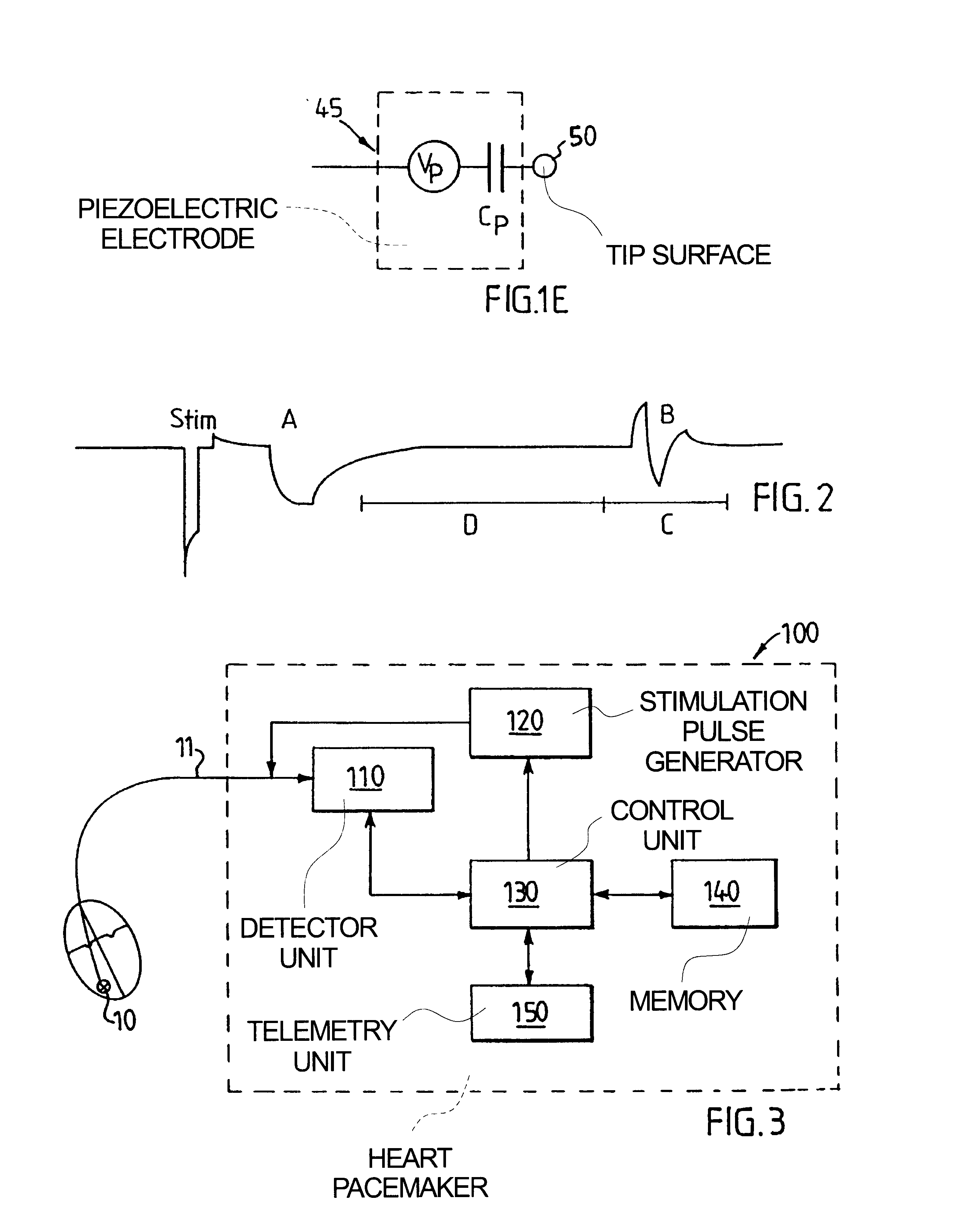
FIG. 2 shows a pulse diagram of the detector input signal generated by the electrode in accordance with an embodiment of the invention and illustrating the stimulation pulse Stim, the electrical evoked response A and the electrical signal B corresponding to the mechanical evoked response. Consequently, a successful heart stimulation will be sensed as two electrical signals by the detector 110 shown in FIG. 3. First the muscle cells close to the electrode will immediately after the stimulation pulse generate an electrical signal A related to the trigged ion transport. Then the global heart muscle contraction will exert a mechanical pressure on the piezo electrode 45 which generates the second electrical signal B. The electrical signal B arrives within a time window C after a certain time D of the electrical signal A. The time interval D depends on the location of the electrode and on the activity of the autonomic nervous syst...

first embodiment

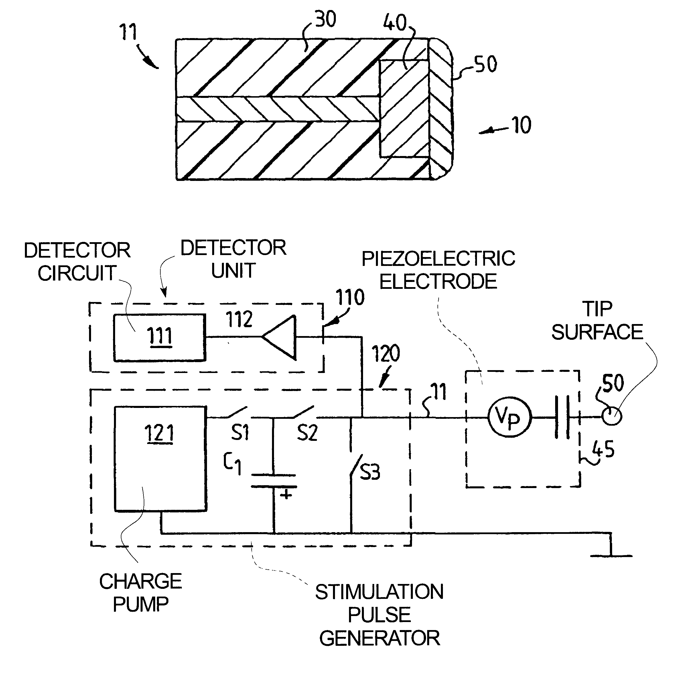
FIG. 4 shows a schematic circuit diagram of a pacemaker in accordance with the invention. The stimulation pulse generator includes a charge pump 121, a capacitor C.sub.1, e.g. 1 .mu.F, and a switch SI which, when closed, charges the capacitor to a voltage of e.g. 20 V. When the stimulation pulse generator 120 rapidly transfers charge to the electrode 10, the thickness of the piezoelectric material 50 changes and pressure waves are emitted to the heart tissue. It is known that mechanical irritation of the endocardium can start a heart contraction, the mechanical stimulation may decrease the threshold for the electrical stimulation or may by itself initiate a heart contraction. Because the piezoelectric electrode 40, 50 functions as a capacitor as well, electrical current is transferred to the tissue when closing the switch S.sub.2. Since the capacitance C.sub.p of the piezoelectric material preferably is 10 to 100 nF, a relatively high voltage of about 5 to 25 volt is needed during a...


PUM


Abstract

In an implantable electrode for an electrode lead for a stimulation device for stimulating tissue, the electrode is formed as a biocompatible piezoelectric electrode which is adapted to be in direct electrical contact with tissue for electrically and mechanically stimulating the tissue and for detecting electrical and mechanical evoked response of the stimulated tissue. The stimulation device can include circuitry for making a diagnosis of a heart condition using signals received from the implantable electrode.

Description

1. Field of the InventionThe invention relates generally to an electrode for implantable stimulation devices such as heart pacemakers or defibrillators. The invention relates further to implantable leads and stimulation devices such as heart pacemakers or defibrillators which employ such an electrode. Moreover, the invention relates to the use of the electrode for diagnosing the condition of stimulated tissue. In particular, the invention relates to an electrode which is adapted to electrically and mechanically transfer stimulation energy to tissue, to an electrode which is adapted to electrically and mechanically receive electrical and mechanical evoked response of the tissue to which stimulation energy has been transferred and to an electrode which is adapted for a combination of the two.2. Description of the Prior ArtThe life span of most pacemakers is dictated by the rate at which their batteries drain. Thus, a substantial effort has been directed toward minimizing the amount of...

Claims


Application Information

Patent Timeline
Patent Type & Authority Patents(United States)
IPC IPC(8): A61N1/362A61N1/05A61N1/37A61N1/365
CPCA61N1/0565A61N1/371A61N1/36585A61N1/362
Inventor HOLMSTROM, NILSHEDBERG, SVEN-ERIKNILSSON, KENTH
Owner PACESETTER AB
Why Eureka
Try Eureka