
Battery charger apparatus

a battery charger and charger technology, applied in the direction of charging/discharging, charging maintainance, electric vehicles, etc., can solve the problems of water use, reduced battery life, and difficulty in having one optimal voltage setting for all conditions

Inactive Publication Date: 2003-02-04
MIXON
View PDF7 Cites 108 Cited by
  • Summary
  • Abstract
  • Description
  • Claims
  • Application Information

AI Technical Summary

Benefits of technology

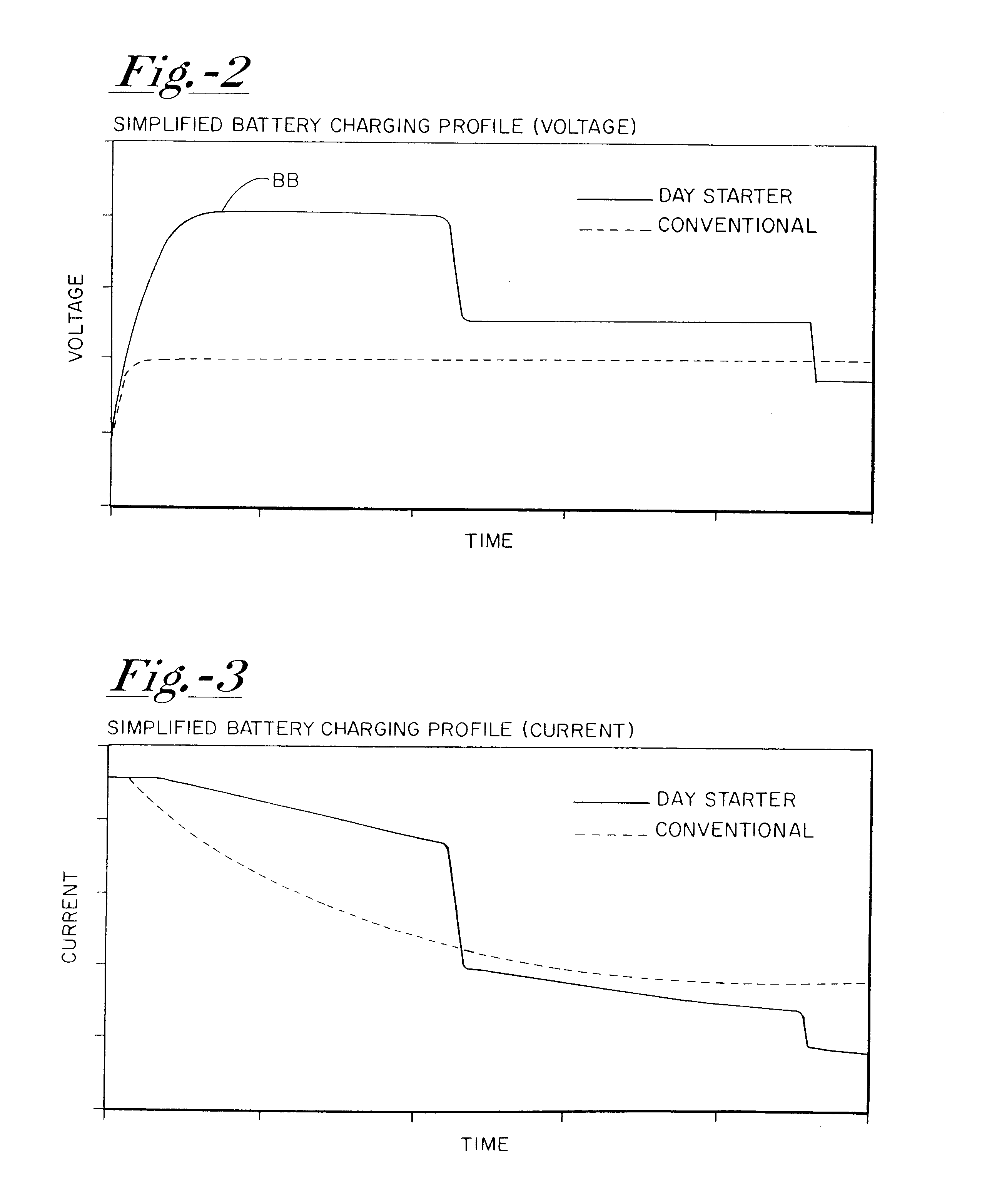
The smart regulator will then regulate the battery's voltage to a second threshold (Tier II). Tier II is in the voltage range of normal voltage regulators (14-15 volts). The regulator keeps the battery at Tier II for a period to ensure that the battery is fully charged, following which the controller tapers back the battery's voltage to a final threshold, or safe-float voltage. This increases fuel economy, battery life, alternator life, and halogen light life. The float voltage is in the range of 13.5 to 14.2 volts, which is the range similar to over-the-road trucks that spend the vast majority of their time running, and not starting.
Application of the '541 invention may include more than one of the described-above thresholds (Tier I, Tier II, Tier III, etc.), some of which may only be used when the controller deems it necessary based on the history of the system. Vehicles that have not run for an extended period are good examples of this. The controller may deem it necessary to add an extra high voltage phase (14.5 to 15.5 volts), in order to break up sulfation on the storage battery's plates and ensure the storage battery is fully charged. This change in charge profile increases the life of storage batteries for recreational boats, recreational vehicles, and other infrequently driven vehicles.
Batteries that have an abnormally low open-circuit voltage are another example of where the controller may need to add an extra or extended high voltage phase (14.5 to 15.5 volts). Leaving headlights or electrical accessories on while the vehicle is not running induces this situation. Present vehicle charging systems are designed to keep storage batteries charged during normal use. They are not designed to fully recharge the storage battery. Often this results in storage batteries spending extended periods significantly discharge, resulting in storage battery plate sulfation and a reduction in battery life. The '541 invention dramatically changes the charging profile to minimize this problem.
It is advantageous for the '541 invention to communicate the information it collects about the charging system to the user and mechanic.
The '541 invention controls a light in the vehicle's dashboard or elsewhere. The light is flashed in two or more simple patterns. The first may indicate all charging parameters normal; the second pattern may direct the user to have the vehicle checked by a technician, thus giving users feedback before serious problems occur.

Problems solved by technology

It is difficult to have one optimal voltage setting for all conditions.
If the voltage setting is too high, overcharging occurs, causing electrolysis (water use) and reduced battery life.
If, however, the voltage is set too low, the battery remains undercharge for extended period, causing sulfation, and reduced battery life.
Temperature, however, is only one factor in the battery's charging needs.
Furthermore, battery temperature and regulator temperature are not often correlated.
The physical placement of the battery is often different than the voltage regulator, resulting in poor temperature correlation.
The majority of voltage regulator prior art ignores the health of the battery, the primary role of the charging system.
Fully charged batteries take seconds to get to the Tier I threshold, while discharged batteries could take tens of minutes.
Leaving headlights or electrical accessories on while the vehicle is not running induces this situation.
They are not designed to fully recharge the storage battery.
Often this results in storage batteries spending extended periods significantly discharge, resulting in storage battery plate sulfation and a reduction in battery life.
Determining a lead-acid battery's SOC is more difficult while the vehicle carrying the battery is in use than while the vehicle is at rest, such as in a garage or parking area.

Method used


Image

  • Battery charger apparatus
  • Battery charger apparatus
  • Battery charger apparatus

Examples


Embodiment Construction

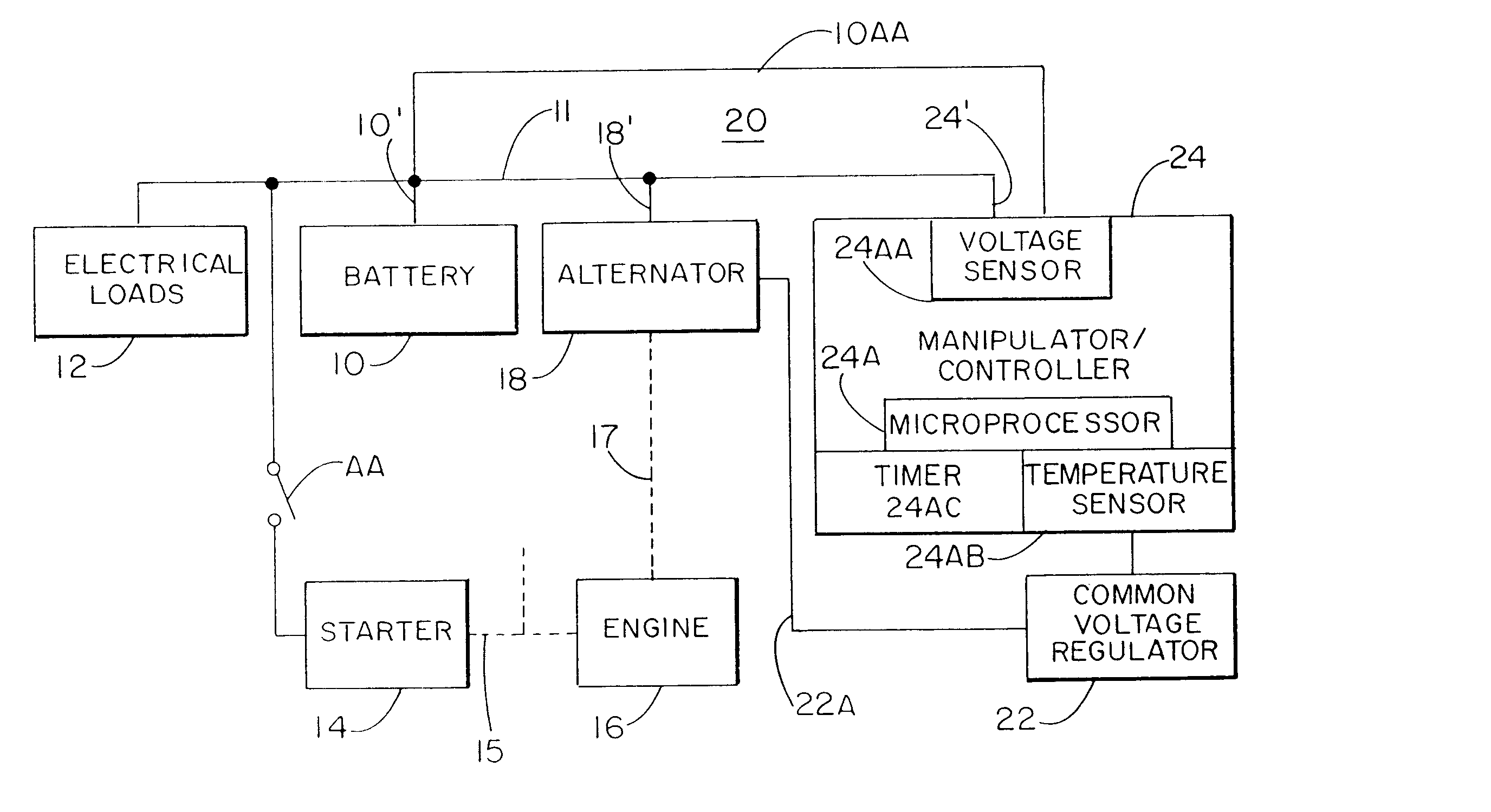
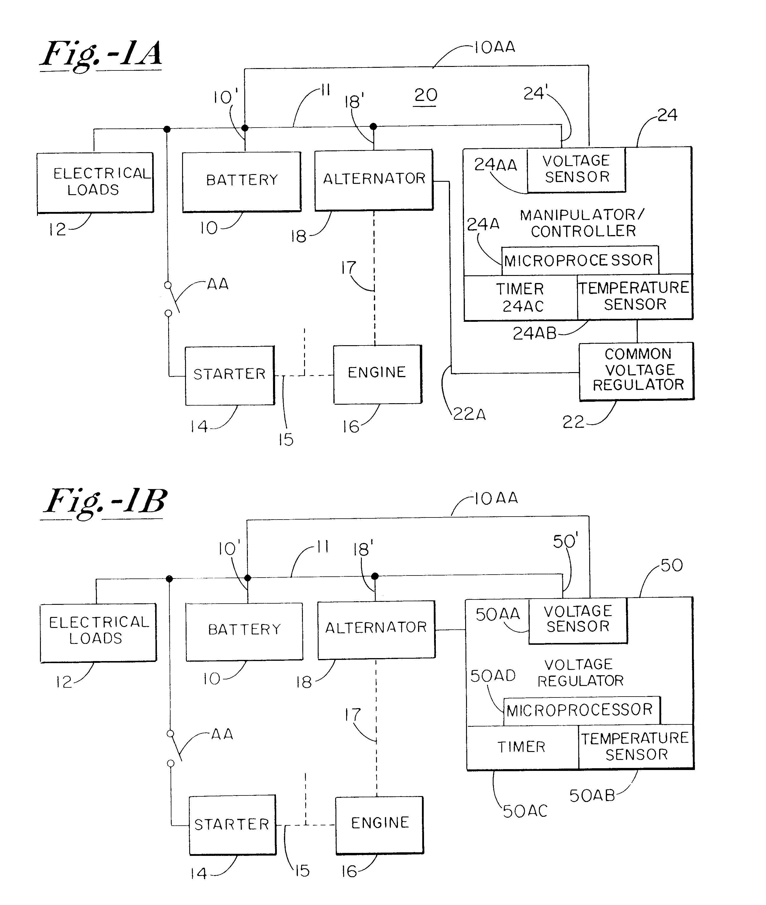
Referring to FIG. 1A, one embodiment of the '541 invention is shown in schematic block diagram form, and comprises a rechargeable battery 10, a plurality of electrical loads 12, a starter motor 14, an engine 16, and an alternator 18. The battery 10 is connected by 10' to a DC bus 11 to supply a plurality of electrical loads 12, as well as to selectively energize the starter motor 14 upon closing of the ignition switch AA. The starter motor is mechanically linked by 15 to the engine 16, the engine further, when operating, causing the rotation of the alternator 18 through the mechanical linkage 17. The invention further includes a voltage regulator 22 and a special manipulator or controller 24 provided by this invention. The voltage regulator 22 may be of any of the several commercially available voltage regulators in widespread use, or a voltage regulator incorporating the present invention's controller technology as disclosed in FIG. 1B. The controlling output for the alternator fro...


PUM


Abstract

A system for actively controlling the charging profile of a battery uses a software-based alternator control unit to control the charging voltage. The system optimizes battery and alternator life. The system, on a dynamic basis, uses battery open-circuit voltage (OCV) to estimate battery state-of-charge (SOC). Also, the charging current of the battery is periodically estimated; this, after processing, provides an estimated SOC of the battery.

Description

BACKGROUND OF THE INVENTIONSThe invention of said prior application, Ser. No. 09 / 549,541, relates to a "smart" voltage regulator for regulating the voltage of an alternator which, in turn, provides a charging current to a storage battery for improving battery performance by maintaining a proper level of charge, and by reducing sulfation on the surface of the plates.By way of background, motor vehicles in the United States some years ago typically had six-volt systems comprising, in part, a battery, a direct current (DC) generator, a DC starting motor or starter which, when energized, would start an internal combustion engine which, in turn, would drive the DC generator. A voltage regulator connected to the DC generator would control the output DC voltage thereof.More recently, most motor vehicles in the United States use twelve-volt systems comprising a twelve-volt battery (12 volt being a nominal output voltage thereof), an alternating current (AC) alternator with appropriate recti...

Claims


Application Information

Patent Timeline
IPC IPC(8): H02J7/00H02J7/14
CPCH02J7/1453H02J7/0075H02J7/0069H02J7/14H02J7/007194H02J7/007192
Inventor MIXON, TIMOTHY S.
Owner MIXON
Learn More