
Method of manufacture of a structural body

a manufacturing method and technology of structural bodies, applied in the direction of auxillary welding devices, soldering devices, ways, etc., can solve the problems of large insertion force, short time period, and easy generation of welding defects, and achieve the effect of short tim

Inactive Publication Date: 2003-02-04
HITACHI LTD
View PDF20 Cites 16 Cited by
  • Summary
  • Abstract
  • Description
  • Claims
  • Application Information

AI Technical Summary

Benefits of technology

This approach ensures good friction stir welding quality and reduces the time required for welding multiple lines by minimizing defects and maintaining tool longevity, even when welding around non-existent or interrupted sections.

Problems solved by technology

When this process is carried out, by removing the first rotary tool from the welding joint at one side of the window and then re-inserting into the welding joint at the other side of the window, a defect in the welding can be generated easily.
Further, at an initial time during the start of the friction stir welding since the temperature of the welding joint has not yet been raised, a large insertion force is required for inserting the rotary tool into the welding joint.
For this reason, the bearing member is required to be large in size, and a problem with the life expectancy of the rotary tool occurs.

Method used


Image

  • Method of manufacture of a structural body
  • Method of manufacture of a structural body
  • Method of manufacture of a structural body

Examples


Embodiment Construction

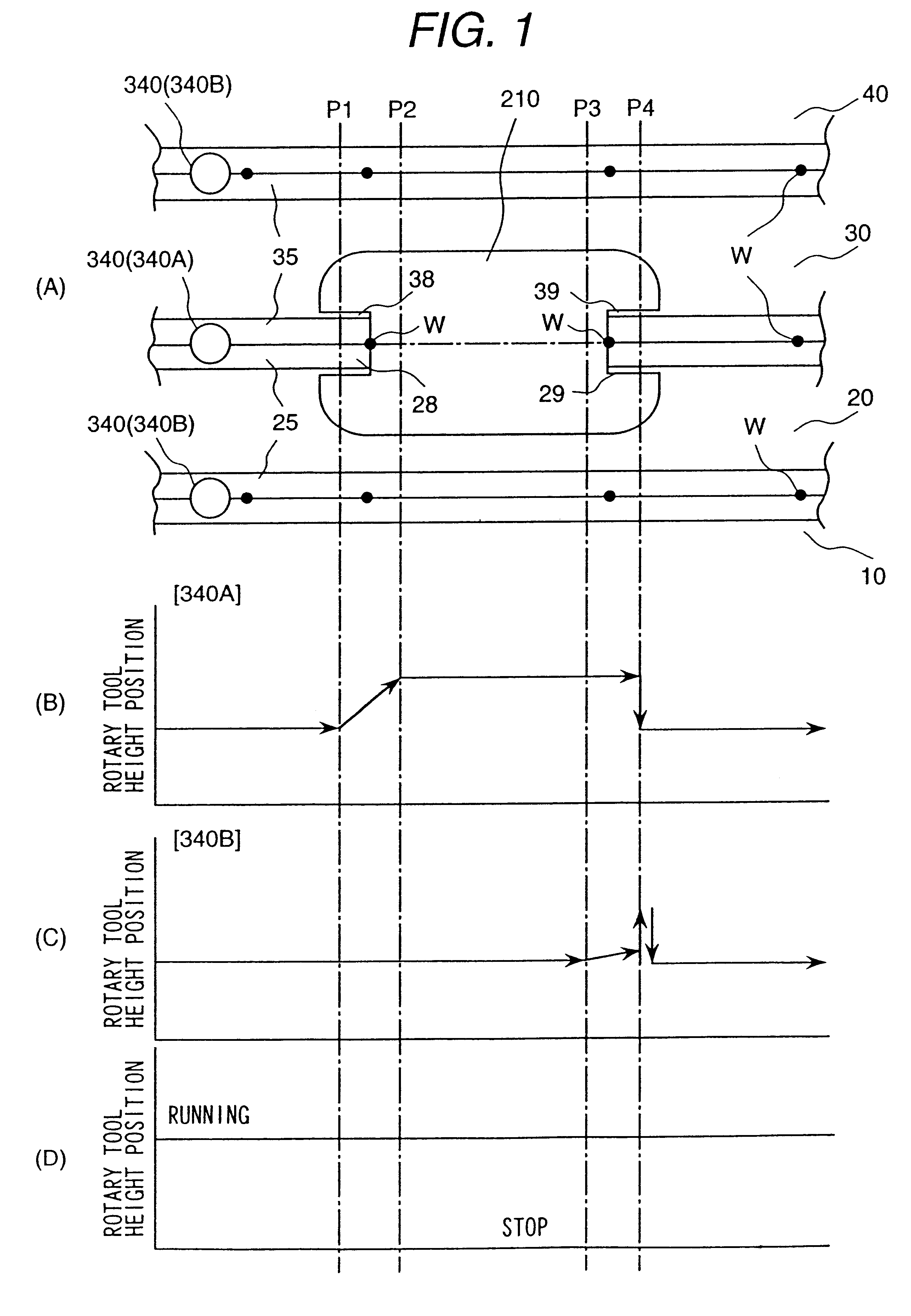
One embodiment of a method of manufacture of a structural body according to the present invention will be explained with reference to FIG. 1 to FIG. 5. As a structural body, a railway car body will be referred to by way of example. As shown in FIG. 5, the car body comprises a side structure 201 for constituting a side face of the car, a roof structure 202 for constituting a roof of the car, a bogie frame 203 for constituting a floor of the car, and an end structure 204 for constituting an end of the car body.

The side structure 201, the roof structure 202, and the bogie frame 203 are constituted respectively by joining plural extruded frame members. The longitudinal direction of each of the extruded frame member is directed in the longitudinal direction of the car body. The material of the extruded frame member is an aluminum alloy.

As shown in FIG. 5, the side structure 201 comprises extruded frame members 10, 20, 30 and 40. In the extruded frame members 20 and 30, a window opening 2...


PUM

PropertyMeasurementUnit
distanceaaaaaaaaaa
depthaaaaaaaaaa
insertion depthaaaaaaaaaa

Abstract

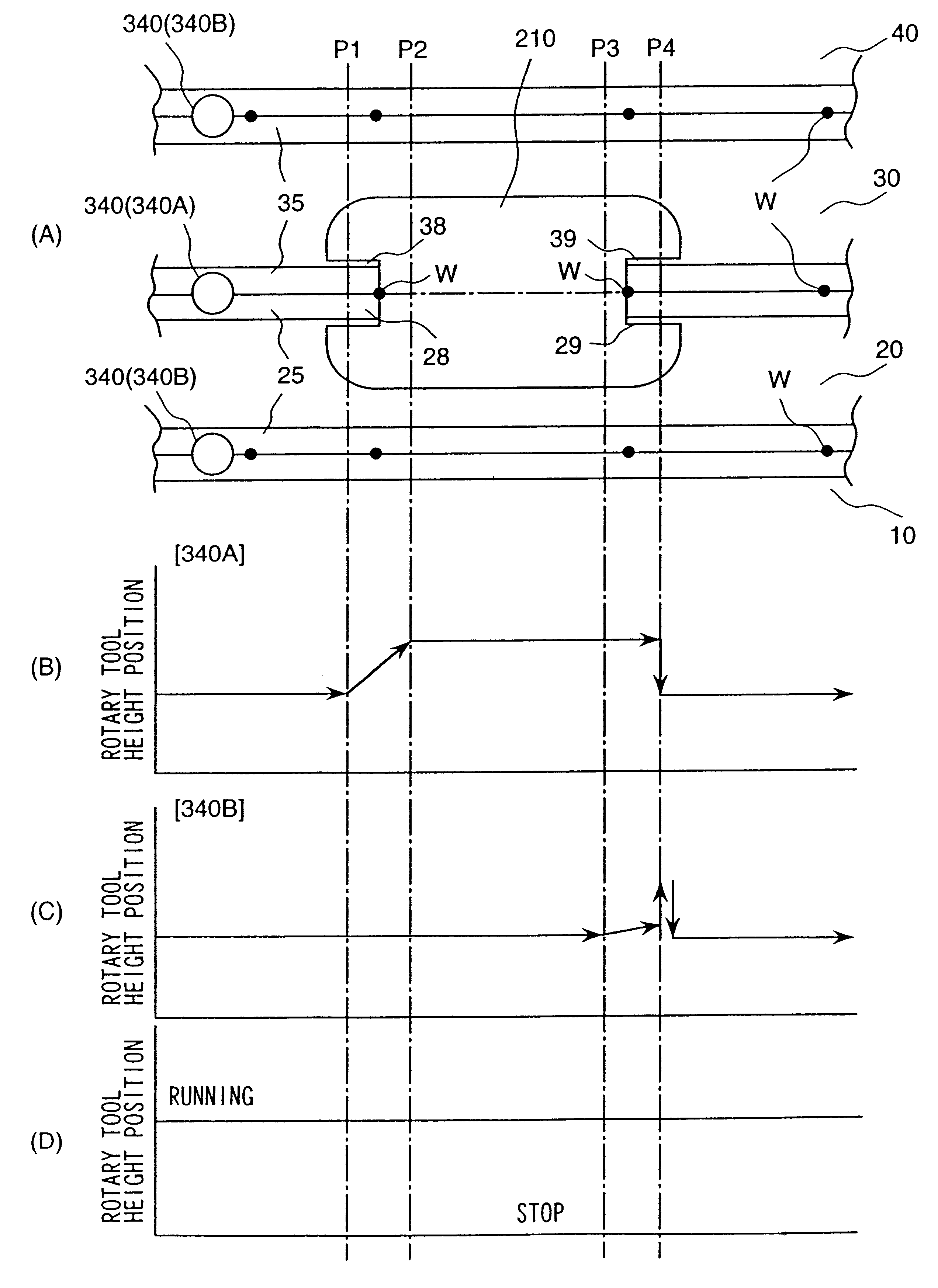
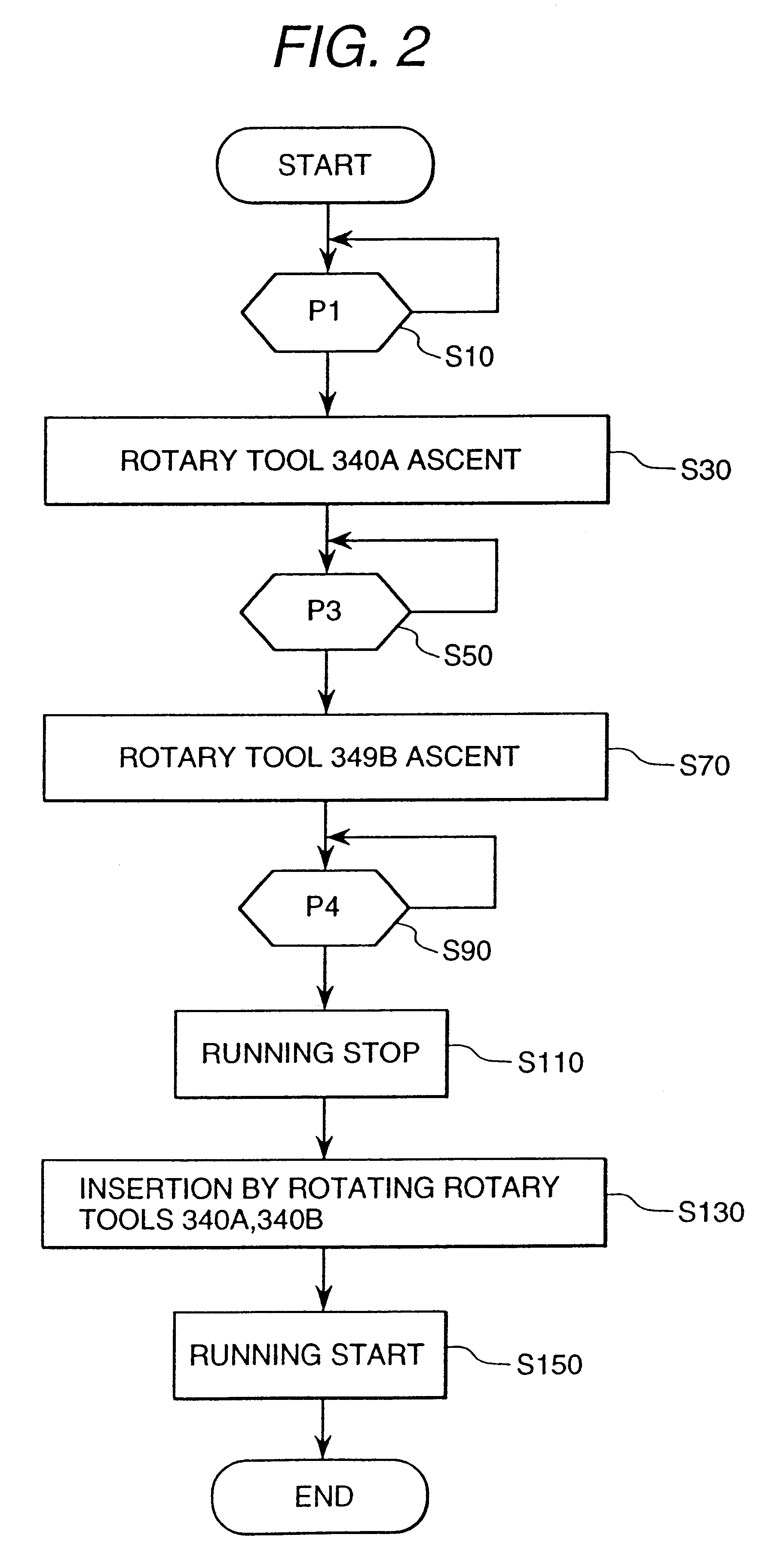
The rotary tools are disposed to weld along two spaced welding lines. The two rotary tools are inserted into respective welding joints and moved at the same time along the respective welding lines. At a position P1 of a portion of a window one rotary tool is withdrawn from the welding joint to that the friction stir welding on that welding joint is stopped although the welding tool continues to move. At a position P3, the rotary tools are gradually withdrawn from their respective welding joints while they continue to move along the welding line. At a position P4, the movement of the rotary tools along the respective welding lines is stopped, the rotary tools are completely withdrawn and the welding is stopped. Next, the rotary tools are inserted into the respective welding joints once again and movement thereof is started again. An insertion amount of the rotary tools at this time is larger than the insertion amount thereof prior to the stopping of the movement of these rotary tools.

Description

The present invention relates to a method of manufacturing a structural body using a friction stir welding method; and, for example, the invention relates to a manufacturing method suitable for the manufacture of a car body of a railway vehicleFriction stir welding is a method wherein a round rod (called a "rotary tool"), which is inserted into a welding joint, is rotated and moved along the welding joint so that the welding joint is heated, softened and solid-fluidized, whereby a solid phase welding occurs.The rotary tool comprises a small diameter portion which is inserted into the welding joint, and a large diameter portion which is positioned outside of the small diameter portion. The small diameter portion and the large diameter portion of the rotary tool have the same axis of rotation. A boundary between the small diameter portion and the large diameter portion of the rotary tool is inserted slightly into the welding joint. The rotary tool is inclined toward the rear relative ...

Claims


Application Information

Patent Timeline
Patent Type & Authority Patents(United States)
IPC IPC(8): B23K33/00B61D17/04B23K20/12
CPCB23K20/122B23K33/00B61D17/04Y02T30/34B23K2201/26B23K2201/045B23K2101/045B23K2101/26Y02T30/00B23K20/12
Inventor EZUMI, MASAKUNIFUKUYORI, KAZUSIGESATOU, AKIHIRO
Owner HITACHI LTD
Learn More